QY CAD user interface
You can quickly learn the name and purpose of different user interface controls by reviewing the following two images of the QY CAD application window, or you can  Take a video tour of the user interface.
To see a set of handy shortcuts for working with the synchronous technology tools in QY CAD, you can download and open the Quick Reference Card in PDF format (qrc.pdf).
The basic user interface
The following example shows the default layout of the QY CAD 2022 user interface for the part file, Moveable Jaw-FOP.par. This part was created in the ordered environment.
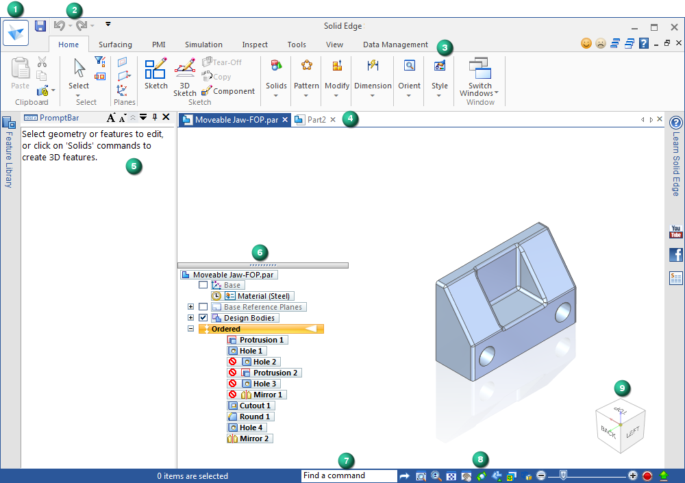
The table identifies and describes each control and provides links to topics that explain how you can use each control.
| User interface object | What does it do? | See this help topic |
|
| Displays the Application menu, which provides access to all document level functions, templates, and standards. Use the Settings tab→Options command on the Application menu to specify units, file locations, colors, and dimension style. You can control helpers, display tooltip videos, and choose a local or web help system. | |
|
| Displays frequently used commands. Use the Customize Quick Access Toolbar arrow shown below to display additional options. | Customize the Quick Access toolbar using the Customize dialog box. |
|
| Organizes commands by tab and by group, per environment. Some command buttons contain split buttons, corner buttons, check boxes, and other controls that display submenus and palettes. Tip: You can use the Customize Quick Access Toolbar→Minimize The Ribbon command to reduce the real estate occupied by the command ribbon. | |
|
| A tabbed document interface in all environments lets you view and switch easily between all of your open document windows. Two different context menus plus tab controls are available. | |
|
| A scrollable, movable docking window that displays prompts and messages related to a command that you select. | |
|
| Provides a quick way to Identify and select model elements. Transitions between ordered and synchronous environments. Tip: PathFinder can be docked or floating. The default form of the PathFinder window is transparent. You can control the appearance of PathFinder in the QY CAD Options dialog box on the Helpers tab. | To learn what the PathFinder icons represent, see Using PathFinder in a part model. |
|
| Locates a command in the user interface. | |
|
| Provides fast access to view-control commands—zoom, fit, pan, rotate, view styles, and saved views. | |
|
| Changes the model view orientation according to what you click on the cube. The Home icon resets the view to the standard isometric view orientation. | |
|
| Opens QY CAD Feedback dialog box that is a part of the QY CAD Product Improvement Program. | |
|
| Provides access to QY CAD Help, tutorials, activities, and videos. | |
| Radial menu | You can use the radial menu to complement the options on the command ribbon, and to consolidate commands that you like to use with a particular workflow.
|


Modeling tools
The following example shows the modeling tools that are available in a synchronous part file. Some of these tools are also available in the ordered (history-based) environment.
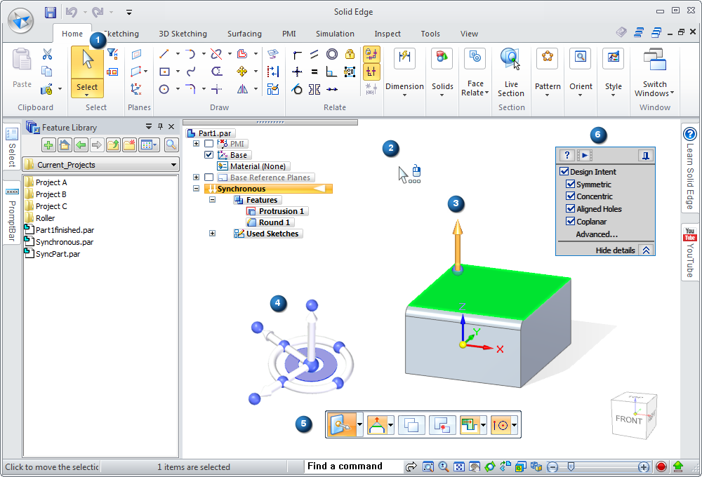
The table identifies and describes each control and provides links to topics that explain how you can use each control.
| User interface object | What does it do? | See this help topic |
|
| Selects 2D and 3D elements and geometry. Displays additional tools based on what you select. | |
|
| Varies according to the command, the step in the command sequence, and what the cursor is pointing to and highlighting. QuickPick displays at the cursor | |
|
| Creates, modifies, or manipulates the selected 2D and 3D elements in a model. | |
|
| Creates and edits model geometry. The steering wheel appears in 2D and 3D configurations, based on what you select. | |
|
| Displays command options and data entry fields for the command in progress. Tip: The command bar is either a floating horizontal bar or a vertical docking window. Use the Helpers tab in the QY CAD Options dialog box to specify the form you want to use. | |
|
| Recognizes relationships between model geometry. You can add or relax constraints to preserve the design intent during edit. | |
|
| Manages your workspace. Contains and organizes tools by including them as tabs in a set of tabs.  |


 when there are multiple elements that can be selected.


© 2021 UDS