Tutorial collection
Select a tutorial that most closely matches what you want to do.
| Subject | Description |
|---|---|
| Create a Part (Synchronous Mode) | Learn how to model parts with synchronous features using QY CAD. This tutorial covers the fundamental modeling techniques for drawing sketches, dimensioning, constructing features, and model editing techniques. Click to begin... |
| Edit a Part (Synchronous Mode) | Learn techniques for modifying parts with synchronous features. This tutorial covers techniques such as applying temporary and permanent relationships between faces using the Relate command, moving faces using the steering wheel, and using Design Intent relationships to control how model modifications are applied. Click to begin... |
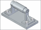
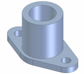
| Vise Base (Hybrid Mode) | Learn how to model solid parts containing both synchronous and ordered features. Click to begin... |
| Part (Ordered Mode) | Learn the basic workflow for modeling parts with ordered features in QY CAD. It covers the fundamental modeling techniques for drawing profiles and constructing features. Click to begin... |
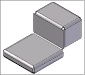
| Sheet Metal Part (Hybrid Mode) | Learn how to model sheet metal parts containing both synchronous and ordered features. Click to begin... |
| Sheet Metal Flanged Part | Learn how to construct ordered contour flanges on a sheet metal part in QY CAD. This tutorial provides step-by-step instructions for constructing different types of contour flanges. Click to begin... |
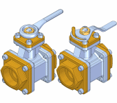
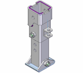
| Slider Assembly | Follow these step-by-step instructions to create an assembly of a slider using Solid Edge. You will use the FlashFit option to apply positioning relationships between assembly components. FlashFit reduces the steps required to position a part using mate, planar align, or axial align relationships. You also learn how to create and add subassemblies to an assembly. Click to begin... |
| Learn techniques for building assemblies in QY CAD. This tutorial introduces assembly creation and editing techniques, such as using the FlashFit option to apply positioning relationships between assembly components. You will use the Select tool and the steering wheel to perform synchronous edits to part geometry while in the context of the assembly. Click to begin... | |
| Alternate Position Assembly | This tutorial demonstrates a typical workflow for creating a family of assemblies with QY CAD. It provides step-by-step instructions for creating a collection of similar assemblies within a single assembly document. You will learn about creating new family members, and the various techniques you can use to make the individual family members unique. Click to begin... |
| 2D Drawings | Learn how to create a simple 2D drawing without a 3D model in QY CAD. You will create 2D geometry, work with layers, change line styles, place and edit dimensions, create formulas between dimensions, and use the other tools available in QY CAD that make the creation and modification of 2D geometry simple. Click to begin... |
| 3D Drawings | Learn how to add dimensions and annotations to drawing views. You will use techniques such as retrieving dimensions from the 3D model and placing various types of dimensions, such as chamfer, distance between, and angle between dimensions. You will also learn how to add center line annotations, callouts that reference hole information in the model, and tolerance information. You will learn how to adjust the placement of dimension and annotation text, terminators, and lines on the drawing. Click to begin... |
| Hole Table | Learn how to use the Hole Table command to create and modify a hole table on a drawing. Click to begin... |
| Use the Create 3D Command | This tutorial provides step-by-step instructions for using the Create 3D command to create a synchronous features in a part model from views in a 2D drawing. Click to begin... |
| Schematic Diagram | Learn the workflow for creating a schematic diagram with QY CAD. You will work with blocks and connectors and use other tools available in QY CAD that make the creation and modification of schematic diagrams simple. Click to begin... |
| Engineering Calculations | Learn a typical workflow for using engineering calculation tools to evaluate a 2D design of a pulley and drive belt system. You will calculate the perimeter of a drive belt, and learn how to change variables using the Goal Seek command to satisfy the design requirements for a pulley and drive belt system. Click to begin... |
| Learn how to model a sheet metal part with synchronous features. As you model this part, you will learn about constructing contour flanges, tabs, flanges, cutouts, jogs, and holes, and using precision drawing aids such as IntelliSketch. Click to begin... | |
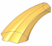
| Swept Feature | Learn how to use the Swept Protrusion command to create a simple feature. Click to begin... |
| Molded Part | This tutorial demonstrates a modeling approach and a suite of commands streamlined for the molded plastic parts industry. You will learn techniques such as adding draft, constructing ribs and web networks, dividing a single part into several smaller parts, and adding lips and grooves. Click to begin... |
| Weldments | Learn a typical workflow for creating weldment-related features. This tutorial provides step-by-step instructions for creating weld features, such as fillet, stitch, and groove welds, using an assembly document. It also covers creating weld-preparation and post-weld machining features, such as chamfers and cutouts. Click to begin... |
| Tube Design | Learn a typical workflow for creating a tube part with XpresRoute. This tutorial provides step-by-step instructions for creating a tube path and tube part. Click to begin... |
| Sheet Metal Feature Library | Learn how to copy and paste features to create a feature library of sheet metal features. Click to begin... |
| Family of Parts | Learn a typical workflow for creating a family of parts. This tutorial provides step-by-step instructions for creating an associative collection of similar parts in different sizes and with different detailing features. Click to begin... |
| Parametric Model | Learn how to define parametric design variables that control dimensions in a part model, and how to define formulas that relate design variables to one another. Click to begin... |
© 2021 UDS

