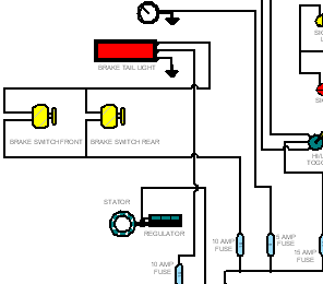
Creating schematic diagrams

This tutorial illustrates the typical workflows for creating block labels, blocks, and connectors in an electrical schematic diagram.
-
A block label is intelligent text that can be placed with a block. You can specify the text properties you want when placing an occurrence of the block, or use property text to automatically capture document-specific attributes such as the document number, file name, and modified date. This application of block labels is useful for automatically updating fields in the title block on a drawing.
-
A block is a named collection of one or more 2D elements or objects that can be selected and referenced as a single entity in a Block Library, or created and used only within the active document. A block consists of both graphics and data.
-
A connector is a type of annotation used to connect blocks and other 2D elements and objects in schematic diagrams, flow charts, and other 2D drawings. You can define the connector shape, edit connector line and terminator properties, and change the orientation of the connector as you are placing it using the options on the Connector command bar.
This tutorial refers to command locations in the QY CAD Draft environment. To find the equivalent location in QY CAD 2D Drafting, use Command Finder, which is located at the bottom of the application window.

To learn how to use Command Finder, see the help topic, Find a command with Command Finder.
This tutorial includes multiple activities. Each activity depends on completion of the previous activity. When an activity is complete, do not exit the tutorial. Continue with the next activity.
© 2021 UDS