Introduction to ordered sheet metal modeling activity
Introduction to sheet metal parts with ordered features
![]()
This tutorial provides step-by-step instructions for creating a model of the sheet metal part shown in the illustration above. As you create this part, you will learn about:
-
Constructing tabs, flanges, contoured flanges, cutouts, and holes.
-
Using precision drawing aids such as IntelliSketch.
Launch the Introduction to ordered sheet metal modeling activity.
Construct a contour flange
-
Open the sheet metal document ...\Program Files\UDS\QY CAD 2022\Training\sessash.psm.
-
Click the Application button
 .
. -
On the Application menu, choose the Save As→Save As command
 .
. -
On the Save As dialog box, save the part file to a new name or location so that other users can complete this activity.
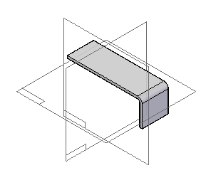
In the next few steps you will construct the contour flange shown.
-
Choose the Home tab→Sheet Metal group→Contour Flange list→Contour Flange command
 .
.The Contour Flange command constructs a series of part faces connected by straight, parallel bends. You begin by drawing a profile (a connected string of lines and arcs), and then project the profile to form part faces and bends.
The system applies material thickness to the faces, offset in the direction you specify, and calculates bend characteristics between the faces.
Select a profile plane
To begin a contour flange, you select a reference plane where you will draw the profile.
-
Position the cursor over the front reference plane, as shown. When the plane highlights, click.
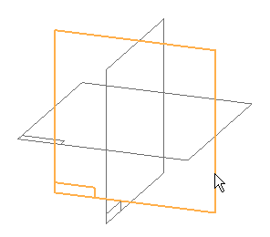
A profile view is displayed, which is oriented to the reference plane you selected.
Start a line
-
The Home tab→Draw group→Line command should be active by default. If it is not, click the Line command from the Draw Group
 .
. -
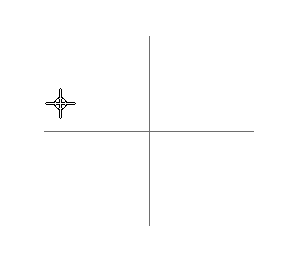
Position the cursor approximately as shown, and click.
Finish the line
-
Move the cursor around in the QY CAD window, and notice that the new line follows the movement of the cursor.
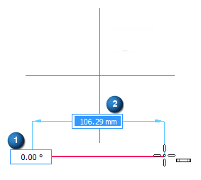
As the cursor moves, notice that the Length and Angle boxes constantly update to reflect the cursor location:

-
Type 100 as the length of the line, and press Enter.
Notice that now, when you move the cursor, the line is always 100 mm, and only the angle changes.
-
Move the cursor to the right, and when the horizontal
 relationship indicator is displayed, click.Note:
For the remainder of this activity, the images will not show the edit handles (1) and (2) that are attached to the sketch elements.
![]()
Draw another line
-
Type 35 as the length of the new line and press Enter.
Note:When you type values you must press Enter for the value to be recognized.
-
Move the cursor down until the vertical
 relationship indicator is displayed, and then click.
 -
After you have finished drawing the second line, right-click to restart the Line command.
![]()
The Line command is still active, ready to draw a new line connected to the first line at its endpoint.
Finish the profile
![]()
-
Choose theHome tab→Close group→Close Sketch command
 .Tip:
.Tip:You can also close the sketch using the Close Sketch icon in the top-left corner of the graphics window.
Choose the side to add thickness to
![]()
An arrow is displayed on the profile you drew. The arrow points up or down, depending on where the cursor is positioned. This arrow shows the side of the profile that material thickness will be added to when constructing the flange.
-
Move the cursor below the profile, and when the arrow points down, click.
Specify the extent of the flange
-
Move the cursor around in the window, and notice that the flange extends to follow the mouse.
Notice that the Distance box constantly updates to reflect the current extent.
-
Type 35 as the extent of the flange, then press Enter.
Position the cursor above the profile, as shown, and click.
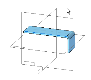
Notice that a bend is automatically inserted between the two faces.
Finish the flange
-
Click the Finish button.
The finished flange is displayed.
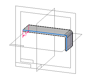
Save the file
-
On the Quick Access toolbar, click the Save button
 to save the work you have done so far.
 -
Press the Ctrl+I keys to rotate the graphics window to the isometric orientation.
Your display should match the illustration.

Construct a tab
![]()
In the next few steps you will add material to the top face of the part.
-
Choose the Home tab→Sheet Metal group→Tab command
 .
.
The Tab command lets you construct a flat shape as the base feature, and it also allows you to add material to existing faces of a sheet metal part. You begin by specifying the plane of the tab, and you then draw a 2D profile in that plane. Finally, the tab is assigned the material thickness of the part.
Select a profile plane
-
Move the cursor slowly over the model, and notice how the faces of the model highlight.
-
Position the cursor exactly over the face shown highlighted in the illustration, stop moving the mouse for a moment, and notice that the cursor image changes to indicate that multiple selections are available.

-
Right-click and the QuickPick tool is displayed.
-
Move the cursor over the different entries in QuickPick, and notice that different faces of the model highlight.
QuickPick allows you to select exactly the face you want, the first time, without having to reject unwanted faces.
-
Use QuickPick to highlight the face shown, and then click to select it.
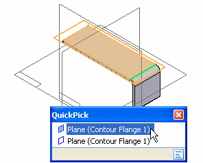
Draw a line
-
The Home tab→Draw group→Line command should be active by default. If it is not, choose the command from the Draw Group
 .
. -
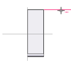
Position the cursor at the top corner of the face, as shown. When the horizontal line highlights and the endpoint
 relationship indicator is displayed, click.
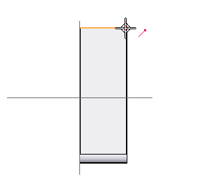
-
Type 65 as the length of the line, and press Enter.
-
Move the cursor to the right until the horizontal relationship indicator
 is displayed as shown, and click.
Draw a line
-
Choose the Fit command to fit the contents of the view to the graphics window
 .
.The Line command is still active, ready to draw another line connected to the endpoint of the last line.
-
Type 65 as the length of the line, and press Enter.
-
Move the cursor to the right until the vertical
 relationship indicator is displayed, and click.
![]()
The endpoint of the line you drew may be outside the window now. Commands for adjusting the contents of the graphic window are located at the bottom-right side of the Solid Edge application window.
![]()
Draw a line
-
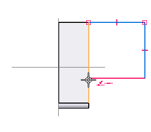
Position the cursor over the edge of the existing face, as shown.
-
When the line highlights and the point-on-element
 and horizontal
  relationship indicators are displayed, click.
 -
When you have finished drawing the last line, right-click to restart the command.
The Line command is still active, ready to draw another line connected to the endpoint of the last line.
Finish the profile
![]()
-
Choose the Home tab→Close group→Close Sketch command
 .
.
Choose the side to add material to
![]()
An arrow is displayed on the profile you drew. The arrow points to one side of the profile or the other, depending on where the cursor is positioned. This arrow shows the side of the profile that material will be added to when forming the tab.
-
Move the cursor to the area enclosed within the profile, and when the arrow points toward this area, click.
Finish the tab
![]()
-
Click Finish.
Material is added to the inside of the profile so that the new tab adjoins the existing face.
Save the file
![]()
-
On the Quick Access toolbar, click the Save button to save the work you have done so far
 .
.
Construct a flange
![]()
You will construct a flange at the left edge of the part, as shown.
-
Choose the Home tab→Sheet Metal group→Flange command
 .
.
The Flange command adds a bend and adjacent new face to the edge of an existing face of a sheet metal part.
The flange you will add next is the simplest case of a flange. It is rectangular, and it extends the full length of the edge it is added to. You will see that Solid Edge lets you construct this flange very quickly.
Select an edge
-
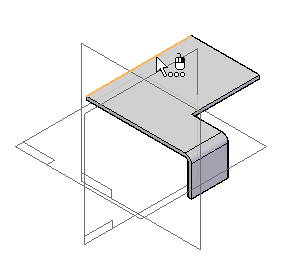
Position the cursor over the left edge of the top face, as shown.
-
When either the top or bottom edge highlights, click.
Set the material reference
![]()
-
Click the Material Outside button
 .
.
The Material Outside option specifies that material equal to the stock thickness is added to the selected edge to form the flange.
Specify the extent of the flange
-
Move the cursor up and down, and notice that a rectangle representing the profile of the new flange follows the cursor movement.
-
Type 35 as the length of the flange, and then press Enter.
-
Move the cursor above and below the starting edge of the flange, and notice that the flange is always 35 mm in height, but it can extend above or below the flange.
-
Position the cursor above the edge, so that the flange extends upward, and click.
Notice that the flange command automatically draws the flange profile for you. Later in the tutorial, you will learn how to modify the default profile.
![]()
Finish the flange
![]()
-
Click the Finish button.
Save the file
![]()
-
On the Quick Access toolbar, click the Save button to save the work you have done so far
 .
.
Construct a flange
![]()
You will construct another simple flange. For this flange, you will also specify corner relief options.
-
Choose the Home tab→Sheet Metal group→Flange command
 .
.
Select an edge
-
Position the cursor over the left edge of the top face.
-
When either the top or bottom edge highlights, click.
![]()
Set the material reference
![]()
-
Click the Material Inside button
 .
.
The Material Inside option specifies that no material is added to the selected edge to form the flange.
Specify the extent of the flange
-
Type 35 as the extent of the flange, then press Enter.
-
Position the cursor below the edge, so that the flange extends downward, and click.
![]()
Set the corner relief options
-
Click the Options button
 .
. -
On the Flange Options dialog box, ensure the Corner Relief option is selected and the Bend Only option is set .

-
Click OK, and the corner relief is applied.
Notice that the corner relief is applied to both adjacent flanges, not the flange you are constructing.
![]()
Notice the default corner treatment where the new flange meets the contour flange you constructed earlier. The corners are not relieved.
Finish the flange
![]()
-
On the command bar, click the Finish button.
Save the file
![]()
-
On the Quick Access toolbar, click the Save button to save the work you have done so far
 .
.
Construct a flange
-
Choose the Home tab→Sheet Metal group→Flange command
 .
. -
Click the Bend Outside button
 .
.The Bend Outside option specifies that material equal to the stock thickness and the bend radius is added to the selected edge to form the flange.
![]()
You will construct another flange, as shown in the illustration. As you construct this flange, you will edit the default profile.
Select an edge
-
Position the cursor over the left edge of the top flange.
-
When either the inside or outside edge highlights, click.
![]()
Specify the extent of the flange
-
On the command bar, type 35 as the extent of the flange, then press Enter.
-
Position the cursor to the left of the edge, so that the flange extends away from the part, and click.
![]()
Edit the profile of the flange
![]()
-
Click the Profile Step
 .
.
The flanges you have constructed so far have all had simple rectangular profiles that extended the full lengths of the edges they were added to.
The flange you are constructing now does not have such a simple profile. You can use the Profile Step on the Flange command bar to edit the default rectangular profile that the system drew for you.
Select geometry to delete
-
Choose the Home tab→Select group→Select command
 .
. -
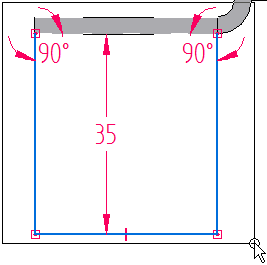
Drag the cursor to create a selection box around the curves making up the flange profile, as shown.
Delete the selected geometry
![]()
Compare the selected geometry in your QY CAD window to the illustration above.
If the geometry you selected does not match the selected geometry shown in the illustration, then try again to select the geometry shown in the illustration. Only the default profile is selectable, so it is okay to drag the cursor across a larger area than necessary.
-
When the geometry you selected matches the illustration, position the cursor in the QY CAD window, then press Delete.
Note:The cursor must positioned over the QY CAD window when you press Delete.
Start a line
-
Choose the Home tab→Draw group→Line command
 .
. -
Position the cursor above the dotted line, approximately as shown. Ensure that no SmartSketch relationships are recognized, then click to start the line.
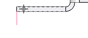
The dotted line represents the connect line: a line, extending the full length of the edge of the part the flange attaches to, that the flange profile must connect with.
Each flange profile must connect with the connect line. However, as long as the first and last lines of the profile cross the connect line and lie between the top and bottom faces of the adjacent part edge, the system will trim the lines and apply the connect relationships automatically.
The connect line is close to, but not coincident with, the bottom face of the part edge.
Finish the line
-
Type 25 as the length of the new line, and press Enter.
-
Move the cursor down until the vertical
 relationship indicator is displayed, and click.
![]()
Draw an arc tangent to the line
-
Click the Arc option
 .
.Four intent zones are displayed at the endpoint of the line you just drew.
By moving the cursor through one of these intent zones on the way to your next click location, you can control whether the new element is tangent to, perpendicular to, or at some other orientation to the element it is connected to.
For example, when drawing a line that is connected to a circle, the intent zones allow you to draw the line tangent to the circle (A), perpendicular to the circle (B), or at some other orientation (C).
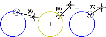
You define the size of the intent zone circle on the Cursor tab on the IntelliSketch dialog box.
The arc will be drawn perpendicularly or tangentially to the line, depending on which of the four intent zones you move the cursor through. Move the cursor through the different intent zones and notice how the arc behaves.
-
Type 12 as the radius of the arc, and press Enter.
-
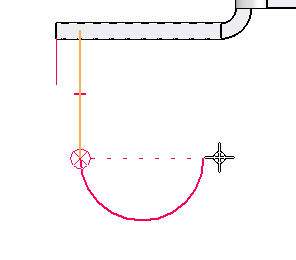
Move the cursor down, through the bottom quadrant of the intent zone, and then to the right, so that the arc curves tangentially to the right. When a dotted horizontal line appears, as shown, click.
Draw a line
-
Click the Line option
 .
.The Line command is still active, ready to draw a line connected to the endpoint of the previous arc.
-
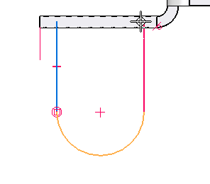
Move the cursor up, vertically from the end of the arc, and notice that the tangent
 relationship indicator is displayed. This indicates that the new line you are drawing will be tangent to the arc you just drew.
 -
Move the cursor up above the connect line—the dotted line just above the bottom face of the part edge—and when the cursor is approximately as shown, click.
 Note:
Note:You may need to use the Zoom Area command to ensure that you place the line properly.
-
When you have finished drawing the second line, right-click to restart the Line command.
Place a dimension
-
Choose the Home tab→Dimension group→ Smart Dimension command
 .
.Smart Dimension dimensions lines and arcs with two clicks. The first click selects a line or arc, and the second places the dimension.
-
Position the cursor over the arc. When the arc highlights, click.
-
Move the cursor above and below the arc, and notice that projection lines, dimension arrows, leader lines, and the dimension text box reposition dynamically, depending on where you move the cursor.
-
Position the dimension as shown, and click. Notice that the dimension text is displayed.
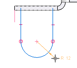
Place and edit a dimension
-
Choose the Home tab→Dimension group→Distance Between command
 .
.This command places linear dimensions that measure distances between elements or key points.
-
Ensure that the Horizontal/Vertical option is set.

![]()
In the next few steps, you will place the dimension shown in the illustration. You will then edit its value to move the flange profile into the proper position.
Select the dimension origin
-
Position the cursor over the left edge of the profile, as shown. When the line highlights, click.
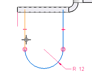
Select the element to measure to
-
Position the cursor over the top edge of the flange, as shown. When the edge highlights, use QuickPick to select it. Notice that either selection in QuickPick is appropriate.
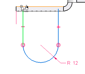
Position the dimension
-
Move the cursor around and notice that the dimension can measure either the horizontal distance between the lines or the vertical distance between the top and bottom endpoints of the two lines. Move the cursor up and down between the top and bottom extents of the lines to toggle the dimension to the horizontal distance.
-
Position the dimension as shown, and click.
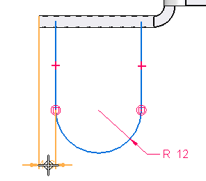
Edit the dimension
![]()
-
In the Dimension Value Edit dialog box, type 4 as the new dimension value, then press Enter. The profile geometry changes to match the new dimension value.

Finish the profile
![]()
When you click the Close Sketch button to close the profile view, watch the profile closely. As the profile view closes, notice that the open ends of the profile are automatically trimmed for you, and the connect relationships are applied, as shown below.
![]()
When drawing flange profiles, both ends of the profile must connect with the connect line. You can do this yourself, or let QY CAD do it for you.
-
Choose the Home tab→Close group→ Close Sketch command
 .
.
Finish the flange
![]()
Since the Bend Outside option was used with this flange, it does not need any additional corner relief applied to it.
-
On the command bar, click the Finish button.
Save the file
![]()
-
On the Quick Access toolbar, click the Save button to save the work you have done so far
 .
.
Construct a hole
![]()
You will construct a hole in the small flange at the back of the part.
-
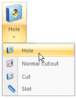
Choose the Home tab→Sheet Metal group→Hole command.
Select a profile plane
-
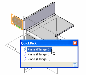
Use QuickPick to select the face shown. The face is on the front side of the flange.
 Note:
Note:Depending on how you constructed your part, the QuickPick options in the illustration might not match the options shown on your screen. Select the face shown in the illustration, whether or not your QuickPick option matches the illustration.
Draw a hole
-
Notice that the Hole Circle command is active by default
 .
. -
Click the Hole Options button
 .
. -
On the Hole Options dialog box, set the Standard to ANSI Metric.
-
On the Hole Options dialog box, set the Size to 10.
-
Set the Through Next option
 .
. -
Click OK on the Hole Options dialog box.
-
Move the cursor across the arc on the flange, and then position the cursor at the center of the arc. When the center point
 relationship indicator is displayed, click.
![]()
Finish the profile
![]()
-
Choose the Home tab→Close group→Close Sketch command
 .
.
Specify the direction to extend the hole
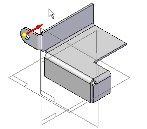
The hole can be extended to the right, to the left, or symmetrically in both directions, depending on where you position the cursor.
-
Position the cursor on the right side of the profile, as shown and click.
Finish the hole
![]()
-
Click the Finish button.
Save the file
![]()
-
On the Quick Access toolbar, click the Save button to save the work you have done so far
 .
.
Mirror and copy the flange and hole
-
Choose the Home tab→Pattern group→Mirror list→Mirror Copy Feature command
 .
. -
Click the Smart button
 .
.
![]()
You will now construct a flange and hole on the other side of the part. You could do this by constructing another flange and hole, following the same steps you used earlier. However, a faster method is to construct a mirrored copy of the flange and hole you constructed earlier.
Select the flange and hole
-
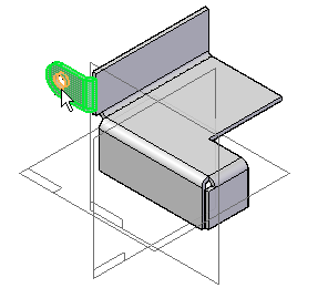
Position the cursor over the flange shown highlighted, then click to select it.
-
Position the cursor over the hole as shown, then click to select it.
-
On the command bar, click the Accept button
 .
.
Specify the mirror plane
-
Click the Parallel Plane option.

-
Select the front planar face on the flange, as shown.
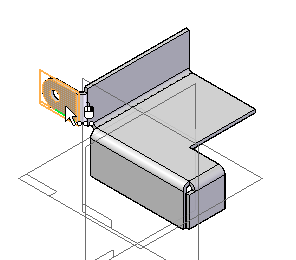
During the Plane Step of the Mirror Copy Feature command, you specify the plane of symmetry for the new mirrored feature. Because there is no plane through the center of the part, you will create a parallel reference plane using a face on the part.
Position the mirror plane
-
Click the Keypoints button, then set the Midpoint option
 .
. -
Position the cursor near the center of the part, as shown. When the midpoint relationship indicator is displayed, click.
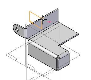
Finish the Mirror copy feature
![]()
-
Click the Finish button.
Save the file
![]()
-
On the Quick Access toolbar, click the Save button to save the work you have done so far
 .
.
Flatten a bend
![]()
You will unbend the flange at the front of the part, as shown in the illustration. Unbending the flange allows you to construct a cutout across the bend.
-
Choose the Home tab→Sheet Metal group→Bend list→Unbend command
 .
.
Select a fixed face
![]()
-
Select the top face of the part.
Select a bend
![]()
-
Select the bend at the front of the part.
Accept the selected bend
![]()
-
Click the Accept button
 .
.
The Unbend command lets you unbend many bends at once. In this case, you will only unbend the one you selected.
Finish unbending
![]()
-
Click the Finish button.
Save the file
![]()
-
On the Quick Access toolbar, click the Save button to save the work you have done so far
 .
.
Construct a cutout
![]()
You will construct a rectangular cutout across the bend that you just flattened.
-
Choose the Home tab→Sheet Metal group→Hole list→Cut command
 .
.
Select the profile plane
-
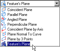
In the Create-From Options list, set the Feature's Plane option.
-
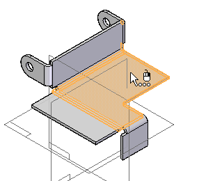
Position the cursor over the tab you constructed earlier in the tutorial, as shown. When the tab highlights, click.
Draw a rectangle
-
Choose the Home tab→Draw group→Rectangle list→Rectangle by 2 Points command
 .
. -
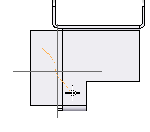
Drag a diagonal line across the flattened bend, approximately as shown. The line you draw represents the diagonal of the rectangle, and the system draws connected lines accordingly.
Dimension the height of the rectangle
-
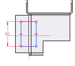
Choose the Home tab→Dimension group→ Smart Dimension command
 .
. -
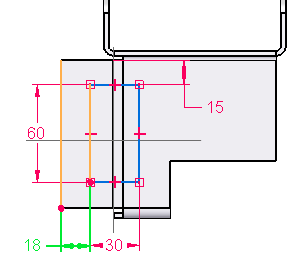
Click the left edge of the rectangle, and place the dimension as shown.
-
In the Dimension Value Edit dialog box, type 60, then press Enter.
Dimension the width of the rectangle
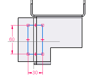
-
Click the bottom edge of the rectangle, and place the dimension, as shown.
-
In the Dimension Value Edit dialog box, type 30, then press Enter.
The Smart Dimension command should still be active.
Dimension the distances between the rectangle and the part edges
-
Choose the Home tab→Dimension group→Distance Between command
 .
. -
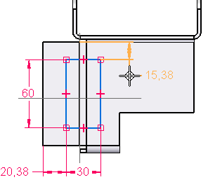
Click the left edge of the flange, then the left edge of the rectangle, and click to place the dimension as shown.
-
Right-click to restart the Distance Between command.
-
Click the top face of the flange, then the top edge of the rectangle, and click to place the dimension as shown in the illustration.
The value of your dimensions may be different than the illustration.
-
Right-click to restart the Distance Between command.
Edit the dimensions
-
Choose the Home tab→Select group→Select command
 .
. -
Edit the values of the dimensions you just placed to match the values in the illustration.
Finish the profile
![]()
-
Choose the Home tab→Close group→Close Sketch command
 .
.
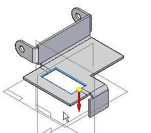
Specify the extent of the cutout
-
Click the Through Next extent option
 .
. -
Position the cursor below the cutout, as shown, and click.
Finish the cutout
![]()
-
Click the Finish button.
Save the file
![]()
-
On the Quick Access toolbar, click the Save button to save the work you have done so far
 .
.
Rebend the flattened bend
![]()
You will rebend the bend you previously flattened.
-
Choose the Home tab→Sheet Metal group→Bend list→Rebend command
 .
.
Select a bend
-
Position the cursor over either end of the flattened bend you just placed a cutout through. When the bend highlights, click to select it.
-
Click the Accept button
 .
.
![]()
Finish rebending
![]()
-
Click the Finish button.
Save the file
![]()
-
On the Quick Access toolbar, click the Save button to save the work you have done so far
 .
.
Chamfer the sharp corners of the part
![]()
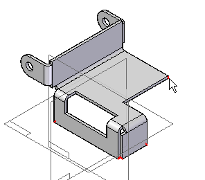
You will place chamfers on all of the sharp corners of the part, as shown in the illustration.
-
Choose the Home tab→Sheet Metal group→Break Corner command
 .
.
Set the chamfer option
![]()
The Break Corner command allows you to create both chamfers and rounds.
-
Set the Chamfer Corner option
 .
.
Select corners to chamfer
-
Set the Select option to Corner.
-
Position the cursor over the five sharp corners shown, and as each corner highlights, click to select it.
-
Type 5 mm in the Break box.
-
Click the Accept button
 .
.
Finish the chamfers
![]()
-
Click the Finish button.
Save the file
![]()
-
On the Quick Access toolbar, click the Save button to save the work you have done so far
 .
.
Edit the material thickness and bend radius
-
Choose the Applications button→Info→Material Table command.
-
On the Gage Properties tab of the Material Table dialog box, set the material thickness and bend radius to 2 mm.

Notice that the width and depth of the bend relief applied to all bends are also editable. These properties are also editable for individual bends; however, if you edit any of these properties for an individual bend, the global properties you see now will no longer apply.
Notice also that a neutral factor of 0.33 was used by default to determine bend allowance at each bend. It is also possible to use bend tables or alternate bend equations to calculate the bend allowance at each bend. See QY CAD Help to learn more about this capability.
-
On the Material Table dialog box, click Apply To Model.
The material thickness and bend radius are recalculated for the entire part.
![]()
Save the file
![]()
-
On the Quick Access toolbar, click the Save button
 to save the completed part.
© 2021 UDS