Constraints
Constraints are limits placed on the model to restrict motion during finite element analysis. Constraints also specify conditions under which a load is applied.
QY CAD Simulation structural analysis supports geometry-based constraints. This means you define constraints indirectly, by selecting model geometry. When analysis begins, the constraints are applied to the nodes or elements that are associated with the selected geometry.
Geometry-based constraints greatly simplify input, particularly in complex solid models.
Links to brief tutorial activities are provided for each type of constraint described below.
Types of constraints
The type of constraint you choose depends upon your model and what you want to analyze. You can apply multiple constraints to the model you are studying.
You can define the following types of constraints:
Thermal studies use the commands in the Thermal Loads group as thermal constrains. A thermal constraint applies a constant temperature to geometry or to nodes. The Temperature, Convection, Heat Flux, and Heat Generation loads can be used as thermal constraints to conduct heat across a model and to dissipate heat. For an example, see the thermal constraints section in the Thermal loads help topic.
You can choose the geometric element type where you want to apply the constraint using the Selection Type list on the Constraints command bar.
Most constraints apply predefined degrees of freedom. However, two types of constraints—cylindrical and user-defined—let you choose the degrees of freedom you want to allow or restrict.
 Fixed constraints
You can define a fixed constraint when you want to remove all three translational degrees of freedom for a solid (with tetrahedral mesh) or all six degrees of freedom for a thin-body part (with surface mesh).
Depending upon mesh type, you can apply a fixed constraint to a face, face set, feature, edge, point, node or curve.
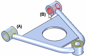
Apply a fixed constraint to part faces which are constrained from moving during the analysis. These would typically be faces which are bolted or fastened to other components in the physical assembly, such as faces (A) and (B). Faces where you applied a load cannot be used as constraint faces.

Nodes and curves are only available for beam mesh types within frame analyses.
Refer to the fixed constraint symbol example in the constraint symbol examples table.
 Pinned constraints
The Pinned command applies a constraint where the three translational degrees of freedom are removed, leaving three rotational degrees of freedom.
You can define a pinned constraint for both a solid and for a thin-body part. For the thin-body part, all three rotational degrees of freedom are maintained.
Depending upon mesh type, you can apply a pinned constraint to a face, face set, feature, edge, point, node, or curve.
Nodes and curves are only available for beam mesh types within frame analyses.
To allow a surface to rotate, apply a pinned constraint to a linear edge on the surface, but not to a point on the surface itself.
Refer to the pinned constraint symbol example in the constraint symbol examples table.
 No Rotation constraints
You can apply a No Rotation constraint to a thin-body part only. It removes the three rotational degrees of freedom, leaving all translational degrees of freedom.
You can apply a no rotation constraint to a face, feature, edge, point, node or curve.
Nodes and curves are only available for beam mesh types within frame analyses.
Refer to the no rotation constraint symbol example in the constraint symbol examples table.
 Sliding Along Surface constraints
The Sliding Along Surface command applies a constraint to a planar face to replicate the sliding-along-a-surface condition. This constraint also can be used when a part is symmetric and contains symmetric support and loading conditions.
This constraint type is not available for beam meshes.
-
When you choose the Sliding Along Surface constraint for a solid, the translation direction perpendicular to the face is constrained.
-
When you choose the Sliding Along Surface constraint for a thin-body part, the translation direction perpendicular to the face is constrained, as are the rotations out of the face. You can clear the Include Rotational DOF option on the Constraints command bar to allow rotation out of the face.
Refer to the Sliding Along Surface constraint symbol example in the constraint symbol example table.
When a part is symmetric, you often can simplify the analysis by analyzing half of the model. This technique is very efficient because it reduces the size of the geometry that is analyzed, which decreases the solve time and obtains more accurate results.
To correctly define the study, however, you must apply the correct boundary conditions to account for the half of the model you omitted. The boundary conditions you apply must force the displacements on the plane of symmetry of the half model to be the same as the displacements that would have occurred in the whole model.
You can apply Sliding Along Surface constraints to multiple planar faces within a single workflow.
 Cylindrical constraints
The Cylindrical command defines how a cylindrical face is constrained with respect to a cylindrical coordinate system. You can control the following types of movement using the Constraints command bar:
-
Radial growth
-
Rotation around cylindrical axis
-
Sliding (translation) along axis
This constraint type is not available for beam meshes.
Refer to the Cylindrical constraint symbol example in the constraint symbol example table.
These constraints can only be applied to cylindrical faces on solid and thin-body models, yet they can be applied to multiple cylinders within a single workflow. In this scenario, each face can have a different axis. The radial, circumferential, and axial directions for each face are based on its own axis.
 User-defined constraints
The User-Defined constraint command provides a flexible definition of degrees of freedom using any rectangular coordinate system in your document.
Depending upon mesh type, you can apply a user-defined constraint to a face, face set, feature, edge, point, node or curve.
Nodes and curves are only available for beam mesh types within frame analyses.
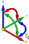
When you choose a user-defined constraint, you use an interactive triad to:
-
Restrict movement in any combination of the three translational degrees of freedom (DOF) for solid parts with tetrahedral meshes.

-
Restrict movement in any combination of the six DOF—three translational and three rotational—for thin-body parts with surface meshes.

To learn how to add and remove DOF using the interactive triad, see the User-Defined constraints examples in the Constraint Symbols help topic.
To learn how to interpret the DOF labels, see the Constraint labels help topic.
© 2021 UDS