Activity: Apply pinned and no rotation constraints
-
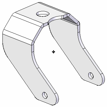
Open the file FE_sheet_fork.psm.
Simulation models are delivered in the \Program Files\UDS\QY CAD 2022\Training\Simulation folder.
-
Create a study:
-
Select Simulation tab→Study group→New Study.

-
From the Study Type list, choose Linear Static, and click OK.
Note:For a sheet metal model, the Mesh Type defaults to Surface.
You can see the new study name on the Simulation tab→Study group.

-
-
Analysis of a sheet metal part (or any thin part) requires a mid-surface.
-
From the Simulation tab→Geometry group, select Mid-Surface.

-
On the Mid-Surface command bar, do the following:
-
Click Offset From Side 1.
-
Ensure Offset Ratio is set to 0.500.

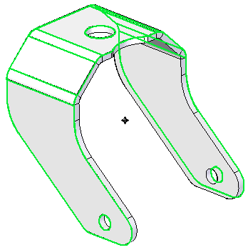
You can see that the part is automatically selected, and the mid-surface is displayed in green.
-
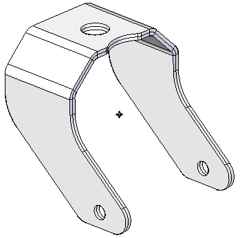
Click the Preview button, and then click Finish.
-
-
-
Select the mid-surface:
-
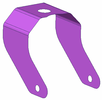
In the empty space in PathFinder, right-click and select Hide All→Design Body.
This exposes just the mid-surface.
 Note:
Note:Although the mid-surface is shown in the default purple color, the remaining illustrations portray a neutral gray color, which makes it easier to see what is selected.
-
From the Simulation tab→Geometry group, select the Define command.

-
Select and accept the mid-surface.

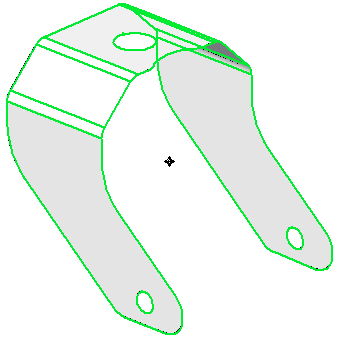 Note:
Note:You also can select the Mid Surface 2 node in PathFinder.
-
-
Apply a pinned constraint:
-
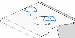
Choose Simulation tab→Constraints group→Pinned.

-
Select the top face.

-
Right-click in space to accept; left-click to finish the command.
-
-
Apply a no-rotation constraint:
-
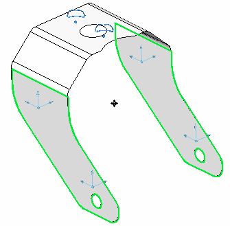
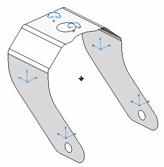
Choose Simulation tab→Constraints group→No-Rotation.

-
Select the two side faces.
-
Right-click in space to accept; left-click to finish the command.
-
-
Close this file.
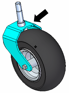
In this activity, you will apply pinned and no rotation constraints to a sheet metal part. The part functions as the wheel support fork on a riding lawn mower.
© 2021 UDS