Constraint labels
You can display constraint labels in the graphics window before generating images of the model. You can turn these labels on and off using the Show Label button  on the Constraints command bar.
Understanding constraint labels
The constraint labels display the following information:
-
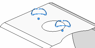
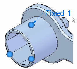
Constraint type is displayed on the edit definition handle, which looks like an annotation with a leader in the graphics window.
Example:Pinned 1, Fixed 1.
-
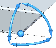
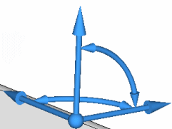
Free degrees of freedom (DOF) are indicated by the value label and the constraint symbol displayed on the model. The constraint symbol arrows point in the directions that are free.
Refer to the examples below.
-
Conversely, the DOF that are omitted from the label, and the constraint symbol arrows that are missing, are the directions that the part is prevented from moving.
Rectangular coordinate system DOF labels
For a rectangular coordinate system, the DOF on the constraint label represent the following:
| Constraint DOF Nomenclature: Rectangular Coordinate System | ||
| Label DOF | Represents | Rectangular Coordinate System Axes |
| 1 | Translation along X | TX |
| 2 | Translation along Y | TY |
| 3 | Translation along Z | TZ |
| 4 | Rotation about X | RX |
| 5 | Rotation about Y | RY |
| 6 | Rotation about Z | RZ |
-
For a shell model, Pinned (No Translation) constraint type, the label is “Free DOF:456.” This matches the constraint symbol: the direction arrows allow rotation in the RX, RY, and RZ.
Conversely, this means the part is constrained in the three translational vectors: TX, TY, TZ. On the constraint symbol, these are indicated by wire frame lines.
-
Three translational and two rotational DOF are free. The label is “Free DOF: 12356.” The label and the constraint symbol indicate that movement is allowed in the TX, TY, TZ, RY, and RZ directions.
-
For a solid model, Fixed constraint type, the label is “Free DOF: None.” The constraint symbol shows no arrows. All directions are constrained.

Cylindrical coordinate system DOF labels
For a cylindrical coordinate system, the DOF on the constraint label represent the following:
| Constraint DOF Nomenclature: Cylindrical Coordinate System | ||
| Label DOF | Represents | Cylindrical Coordinate System |
| 1 | Translation along Radial (Radial Growth) | TR |
| 2 | Translation along Theta | TT |
| 3 | Translation along Z | TZ |
| 4 | Rotation about Radial | RR |
| 5 | Rotation about Theta | RT |
| 6 | Rotation about Z | RZ |
The following example compares the Cylindrical constraint DOF label for a solid model and a thin-body model.
-
A solid model can be constrained in the TR, TT, and TZ directions. When Translation along Radial (Radial Growth) is constrained, the label is “Free DOF: 23.”
-
A thin-body model can be constrained in all six directions. When Translation along Radial (Radial Growth) is constrained, the label is “Free DOF: 23456.”
© 2021 UDS