Define a load
-
Choose one of the following load commands from the Simulation tab based on study type (structural studies or thermal studies)—and mesh type:
- In the Structural Loads group:
-
-
For an example, see Tutorial: Simulate forces on an I-beam.
-
For an example, see Tutorial: Simulate pressures in a tank.
-
For an example, see Activity: Apply a torque load.
-
For an example, see Tutorial: Compare displacement load results for different materials.
-
For an example, see Activity: Apply a bearing load.
-
Moment (for beam mesh types)
To learn how to create a study for a structural frames model, and to apply forces along beams at nodes and curves, see Tutorial: Simulate stresses on a bridge.
See the Structural and body loads help topic.
-
- In the Body Loads group:
-
-
For an example, see Activity: Apply a body temperature load.
-
For an example, see Activity: Apply a centrifugal load.
-
For an example, see Tutorial: Perform a thermal stress analysis.
See the Structural and body loads help topic.
-
- In the Thermal Loads group:
-
See the Thermal loads help topic.
- In the External Loads group, use these commands to apply FLOEFD fluid flow results to your QY CAD Simulation study:
-
-
Import Fluid Pressure
-
Import Fluid Temperature
-
-
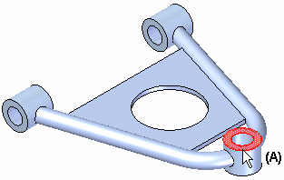
Follow the instructions in PromptBar to select the model entities or elements where you want to apply the load.
Example:These would typically be the faces which carry the load in the physical assembly (A).

The geometry you can select depends on model type and mesh type. You can select:
-
Faces or face set
-
Surfaces
-
Edges
-
Points
-
Features or design bodies
-
Nodes (Beam mesh only)—To learn how to create nodes, see Define a node.
-
Beam curves (Beam mesh only)
For some load types, you can change the element type and key point selection type on the Loads command bar.
-
-
Enter the load value in the dynamic input box as appropriate.
Example:-
(For a Force load) This shows the default value and units when defining a Force load:

-
(For a Centrifugal load) Type two values. Either value can be zero, but both cannot be zero at the same time. A zero value turns the load symbol off.
-
(Angular Velocity) Angular Rotation/Time, for example, deg/sec.
-
(Angular Acceleration) Angular Rotation/Time², for example, deg/sec².
-
-
(For a Bearing load) Type two values:
-
(Force Value) The bearing force value is applied equally to multiple selected faces.
-
(Load Angle) The load angle, combined with the load value and the surface normal, determines the area in which the bearing is in contact with a given surface.
-
-
(For a Torque or Moment load) Type a value for force distance. You can enter units of foot-pounds force or newton meters.
-
(For a Radiation load) Click the Options button on the command bar, and then choose the radiation load type and specify radiation load values using the Radiation Load Options dialog box.
Tip:-
Radiation loads also require a corresponding Body Temperature load. This ensures that all nodes and elements are assigned a default temperature, even when no load is specifically applied to them.
-
For some load types, you can use the Total Load option
 on the command bar to distribute the load value proportionally among multiple entities.
-
-
Define the load direction using one of the following methods:
-
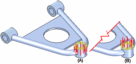
To reverse the load direction180 degrees, click Flip Direction on the command bar.
Example:When applying a pressure load, a default load direction is selected (A). You can flip the load direction (B).

-
Use the loads directional steering wheel.
-
To specify the load direction without using the steering wheel, or when you do not know the total magnitude of the load:
-
On the Loads command bar, from the Direction Type list, choose the Components option
 .
. -
From the Coordinate System list
 , select the coordinate system to reference, such as the Base coordinate system.
 -
In the dynamic input box, type the X, Y, and Z load direction component values.
Note:Thermal loads and some other load types do not use a direction vector.
-
-
-
If the preview is acceptable, right-click or press Enter to accept the load.
-
Click to finish the command.
-
When you create a displacement load, NX Nastran also requires a constraint on the part. You can satisfy this requirement using the Pinned option
 on the Loads command bar. This automatically creates a pinned constraint along with the displacement load.
 -
In a steady state heat transfer study, a thermal temperature load applied to one face or surface does not show a temperature distribution across the model unless a second thermal load is applied to the opposite face or surface. The second load allows the heat energy to be conducted across the part. See Defining thermal studies in the Thermal studies help topic for examples.
-
You can use the Select tool, QuickPick, drag select, or the Selection Manager to select model geometry.
-
Before you finish the command, you can make adjustments on the Loads command bar to:
-
Change the appearance of load symbols.
-
Display the value label.
-
For a bearing load, use the Traction load option
 to specify whether the load pulls or pushes on a surface.
-
-
Default value units and precision are defined in the File Properties dialog box, which you can open from the Application menu
 . If you enter a value in units other than the default units, the value is converted automatically to the default unit type.
© 2021 UDS