Data tab
Sets the formatting options for data in tables and parts lists. You also can use shortcut commands to edit the data cells on this tab. To learn how you can use these options to format your table or parts list, see Using the Data tab.
- Insert Column
-
Displays the Insert Column dialog box, which you use to insert columns in the table.
You also can right-click a column and select Insert Columns to display the Insert Columns dialog box.
- Delete Column
-
Deletes the selected column from the table.
You also can right-click a column and select Delete Columns to delete the column.
- Format Column
-
Displays the Format Column dialog box, which you use to change the format for the column.
You also can right-click a column and select Format Column to display the Format Columns dialog box.
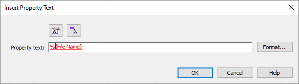
- Insert Property Text

-
Opens the Insert Property Text dialog box to choose the type of associative text you want to add to the table cell.
This option is available in a user-defined table cell, and when you create a column for user-defined content in a model-derived table, such as a parts list.
- —To reference custom or standard properties associated with the active document, or exposed variables in the Variable Table, select the Insert Property Text button to open the Select Property Text dialog box.
-
 —To reference PMI annotations and other annotations on the drawing sheet, select the Reference Text button to open the Select Reference Text dialog box. For more information, see Create reference text.
 -
After you insert the associative text into the Property text box, you can format the output value (the extracted value) of the associative text by clicking inside the string and selecting the Format button. Only the options that are valid for formatting the string are available in the Format Values dialog box.
Property text is associative text that is updated when you select the Home tab→Property Text group→Update All command.
-
- Font
-
Specifies the font type to apply to the currently selected data cell, or to all the cells in the column if the column header is selected. All installed fonts are available, such as QY CAD ISO, Arial, Calibri, Microsoft Sans Serif, Times New Roman, and Tahoma.
Note:The default font, font style, font size, color, and other properties are defined in the table text style associated with the current table style. To learn about table styles and how to change the properties associated with them, see the following Help topics:
- Font Style
-
Specifies the font style to apply to the currently selected data cell, or to all the cells in the column if the column header is selected.
You can use the three buttons in the Font Style section individually, or you can combine them to create additional font styles, such as Bold Italic.
- Bold
-
Makes text boldface.
- Italic
-
Italicizes text.
- Underline
-
Underlines text.
- Horizontal justification
-
Adjusts the horizontal alignment of the text within the currently selected data cell, or all of the cells in the column if the column header is selected. The options are Left, Center, and Right.
The default is for text to be centered.
- Vertical justification
-
Adjusts the vertical alignment of the text within the currently selected data cell, or all of the cells in the column if the column header is selected. The options are Top, Center, and Bottom.
The default is for text to be at the top.
- Format
-
Opens the Format Values dialog box for you to apply unit, round-off accuracy, and tolerance formatting to one or more selected data cells in a hole table. For example, dowel holes may require a finer round-off compared to threaded holes.
This option is only available for hole tables.
- Insert Row
-
Displays the Insert Row dialog box, which you use to insert rows in the table.
You also can right-click a row and select Insert Rows to display the Insert Rows dialog box.
- Delete Row
-
Deletes a row from the table.
You also can right-click a row and select Delete Rows to delete the row.
- Move Row Up
-
Moves the selected row up one row.
Note:This option does not apply to hole tables. Instead, use the Move Row Up button on the Hole Number tab.
- Move Row Down
-
Moves the selected row down one row.
Note:This option does not apply to hole tables. Instead, use the Move Row Down button on the Hole Number tab.
-
Parts lists
The row manipulation features are not available for system-generated parts lists.
-
Family of parts tables
-
When you create a new family of parts table, data is not displayed on this page until you have selected the table variables on the Variables page of the Family Of Parts Table Properties dialog box and clicked OK.
-
If a row contains values that are underlined, this indicates a family of parts table value in the master document was changed, and the change was not applied to the family members using the Save Table Data button in the Family of Parts Edit Table dialog box.
-
If a row contains values that are underlined, this indicates a value in the Family of Parts Edit Table in the master document was changed, but the change was not applied to the family members using the Populate Members button or the Apply Member button. To update the drawing table, the changes must be applied in the master document.
-
© 2021 UDS