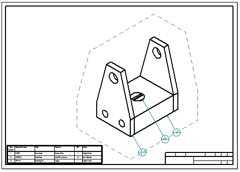
Workflow to create an assembly drawing with a parts list
You can choose model representations defined in the assembly model to show in a drawing view, such as an exploded model display configuration or a PMI model view. Use the following process to create an isometric drawing view of an assembly with a ballooned parts list. You can do this from the assembly model or from a draft document.

-
Start the Drawing View Wizard
In the assembly document, do the following:
-
Save the assembly document.
-
From the Application menu, select the New→Drawing of Active Model command.
-
In the Create Drawing dialog box, select the Run Drawing View Creation Wizard check box and click OK.
-
-
Choose an assembly model representation
Select the Options button on the View Wizard command bar to open the Drawing View Creation Wizard (Drawing View Options), and then select one of the following from the .cfg, PMI model view, or zone list:
-
To create an exploded isometric model view, select an exploded model display configuration
 . To learn how to create an exploded model configuration, see Explode an assembly automatically.
 -
To communicate design, manufacturing, and functional information that has been added to a saved view of the model, select a PMI model view name
 . To learn how to create a PMI model view, see Create a PMI model view.
 -
To create a user-defined view of the equipment and components in a rectangular area of a large assembly model, select a zone name
 .
. -
If there is no predefined model representation to select, or to create any combination of user-defined assembly views, select No Selection.
-
-
Place the initial view
By default, the initial view of an assembly model is an isometric view. You can place that view, or you can change to a different view of the model by selecting the View Orientation button
 on the View Wizard command bar.
 -
Apply formatting to the drawing view
After placing the view, you can select it and modify it using options on the Drawing View Selection command bar.
For example, you can open the Drawing View Properties dialog box and use the Display tab (Drawing View Properties dialog box) to control the display of the individual parts and subassemblies in the assembly.
-
Retrieve model dimensions and annotations
-
If the drawing views are orthographic, you can use the Retrieve Dimensions command to extract dimensions and annotations from the model onto the drawing.
-
If the drawing views are pictorial (isometric, dimetric, or trimetric), you can use the Smart Dimension command to Place a 3D dimension on a pictorial drawing view.
-
-
Add a ballooned parts list
Use the Home tab→Tables group→Parts List command to Create a parts list.
-
You can insert sheets into the draft file, and then create additional drawing views–assembly part views—that document the individual components, parts, and subassemblies in the assembly model. You can add auto-balloons on the part views that match the parts list on the full assembly. To learn how to do this, see Create assembly part views with the View Wizard.
-
You can rearrange balloons that have been generated automatically with a parts list, so that all of the balloons are visible. For more information, see Arranging annotations using alignment shapes.
-
If parts are missing in a parts list or a drawing view for an assembly, verify that the missing parts are not turned off in the assembly document Occurrence Properties dialog box. To learn how, see Display assembly occurrences in a drawing view or parts list.
-
To place a parts list that shows the assembly model item numbering schema in the table and in the balloons, select the Use assembly generated item numbers check box on the Options page (Parts List Properties dialog box. If this option is unavailable, you need to set the Create item numbers check box on the Item Numbers page (QY CAD Options dialog box).
-
You can create a parts list using the simplified versions of assemblies and subassemblies. To do this, select the Use simplified assemblies option on the List Control tab in the Parts List Properties dialog box.
-
You can create a drawing view of an alternate assembly.
© 2021 UDS