Create a PMI model view
All the information contained in the model currently displayed in the graphics window is copied to the model view created here. For example, if PMI dimensions, annotations, and 3D sections are shown in the view, then those will be included in the PMI model view.


-
Use the standard view selection and model rotation tools to display the model face or pictorial view that you want to show in the 3D model view. For example, you can use the View tab→Look At Face command
 to display the top face of the model.
 -
Choose the PMI tab→Model Views group→View command
 .
.This copies all the model display settings and attached dimensions and annotations to the new model view and displays the Model View Options dialog box.
-
In the Model View Options dialog box:
-
(Assign view name) Type a model view name in the Name box.
Model view names must be unique within the document.
-
(Set render mode) From the Render Mode list, select a render mode for the model view. To keep the current render mode, select None.
-
(Optional) When including a 3D section in the model view, from the Cut Display list, select a section display option, and then set or clear the Show Cutting Plane option as desired.
-
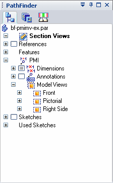
Click OK to generate the model view definition and add it to the Model Views collection on the PathFinder tab.


-
-
To create another PMI model view, change the view orientation of the model as desired, and select the View command again.
-
(Apply a view to the model) If you have multiple PMI model views, right-click a model view name on PathFinder, and then choose Apply View.
You can create a drawing view showing all of the information you captured in the PMI model view. For more information, see Create a PMI drawing view.
© 2021 UDS