Activity: Move a face and construct a flange
Move a face and construct a flange
In this activity, you will move a face and then learn how to construct a flange.
Launch the Activity: Move a face and construct a flange.
Move a sheet metal face
![]()
You can move a sheet metal face, as shown in the illustration.
-
Choose the Home tab→Select group→Select command
 .
.
Select a thickness face
![]()
To move a face, you start by selecting a thickness face on the part.
-
Position the cursor over the left thickness face of the part, as shown above, then click to select it.
A handle is displayed on the face you selected (1), and the Move command bar is displayed in the graphics window (2), as shown below. You will learn more about these tools in the next step.
![]()
Learn more about the on-screen tools
![]()
When you select a thickness face on a sheet metal part, there are several actions you can perform.
You can use the Action list on the command bar (1) to:
-
Move the thickness face to change the size of the part.
-
Construct a flange.
-
Define a relationship between the selected face and other faces on the model.
You can use the handle on the selected face to:
-
Move the selected face by clicking the long arrow on the handle (2).
-
Construct a flange by clicking the short arrow on the handle (3).
Select the long arrow on the handle
-
Position the cursor over the long arrow on the handle, as shown, and then click to select it.

-
Move the cursor slowly to the right, then to the left.
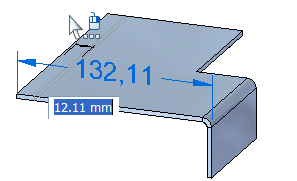
Notice that the face moves along with the cursor.
Define the extent of the move operation
-
Position the cursor to the left such that the face is approximately 20 millimeters longer, as shown, then type 20, and press the Enter key to precisely define the move distance.
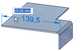
The model updates as shown.
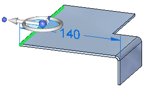
-
Position the cursor away from the part and click to complete the movement operation.
Fit the view
![]()
-
Choose the Fit command
 to fit the contents of the view to the graphics window.
Construct a flange
![]()
You will construct a flange at the left edge of the part, as shown in the illustration. You construct these types of flanges using the Select tool.
-
Choose the Home tab→Select group→Select command
 .
.
The flange you will add is the simplest case of a flange. It is rectangular, and it extends the full length of the thickness face to which it is added. You will see that you construct this flange very quickly.
Select a thickness face
You construct flanges by selecting a thickness face on the part.
-
Position the cursor over the left thickness face of the part, as shown, then click to select it.
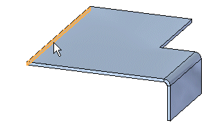
Select the short arrow on the handle to construct a flange
-
Position the cursor over the short arrow on the handle, as shown, and then click to select it.
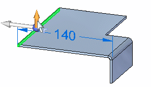
A new flange is attached to the cursor, and the Flange command bar is displayed as shown below. As you move the cursor, the length of the flange updates dynamically.
![]()
Specify the extent of the flange
-
Move the cursor around in the window, and notice that the flange length updates dynamically to follow the cursor.
-
Position the cursor above the part, as shown, and then in the flange extent dynamic input box, type 40, and then press Enter.
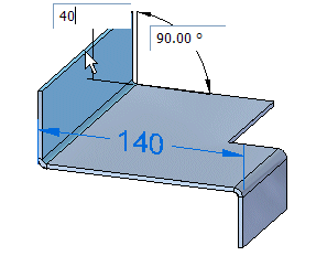
Save the file
![]()
Your flange should match the illustration.
-
On the Quick Access toolbar, click the Save button
 to save the work you have done so far.
© 2021 UDS