Activity: Construct a tab
Construct a tab
![]()
In the next few steps you will add material to the top face of the part.
First you will draw a sketch, then you will use the Select tool to extrude the sketch into a solid Tab feature.
Launch the Activity: Construct a tab.
Start the Line command
![]()
-
Choose the Home tab→Draw group→Line command
 .
.
Lock sketch input to a model face
-
Position the cursor over the planar face shown.
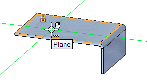
Notice the following:
-
The planar face highlights.
-
A lock symbol is displayed adjacent to the cursor.

-
A Tooltip appears.
-
-
Press the F3 key on the keyboard to lock sketch input to the selected face.
Notice that a locked plane indicator is displayed in the top-right corner of the graphics window, as shown.

Also notice that when you move the cursor over the other model faces, they no longer highlight. All sketch input is now locked to the selected model face.
When drawing sketches, you can lock sketch input to a specific planar face on the model. This can be useful when you want to draw outside the area defined by the planar face.
You can lock cursor input to the sketch plane using the lock symbol displayed adjacent to the cursor, or you can use a shortcut key.
Draw a line
-
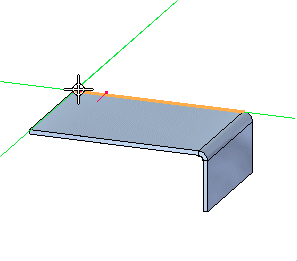
Position the cursor at the top corner of the model face, as shown. When the long model edge highlights and the endpoint relationship indicator
 appears, click to start the line.
-
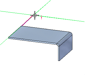
Move the cursor until:
-
The vertical relationship indicator is displayed as shown below.
-
The line Length is approximately 80 millimeters.
-
The Line Angle is exactly 90 degrees.

-
-
Click to finish the first line.
Draw another line
-
Move the cursor until:
-
The horizontal relationship indicator is displayed, as shown above.
-
The line Length is approximately 80 millimeters.
-
The line Angle is exactly 0 degrees.
-
-
Click to place the line.
![]()
The Line command is still active, ready to draw another line connected to the endpoint of the last line.
Draw another line
-
Move the cursor until:
-
The point-on and vertical relationship indicators
 display adjacent to the cursor, as shown above.
 -
The line Angle is exactly -90 degrees.
-
-
Click to place the line.
-
After you have finished drawing the third line, right-click to restart the Line command.
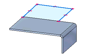
The third line is placed, as shown. Notice that the area enclosed by the three lines and the model edge is displayed shaded.
![]()
Observe the results
![]()
Take a few moments to observe the finished sketch.
In QY CAD, when 2D elements form a closed area, they are called sketch regions.
This indicates that the sketch is valid for constructing a feature using the Select tool. Although this sketch is not closed, it is treated as a sketch region because the linear model edge at the bottom of the sketch closes the gap between the three lines on the sketch.
Also notice the relationship symbols where the lines connect to the solid model, and at the midpoint of lines.
Although the sketch and the relationships are discarded when you construct the next solid feature, building these relationships into the sketch is helpful. When you construct the solid feature, these 2D relationships orient the faces that are constructed from the sketch, and help define the behavior you want when editing the solid feature later.
Unlock the sketch plane
![]()
Since you are finished drawing sketch elements, you will now unlock the sketch plane.
-
With your cursor in the QY CAD window, press the F3 key on the keyboard to unlock the sketch plane.
Start the Select command and select the sketch region
-
Choose the Home tab→Select group→Select command
 .
. -
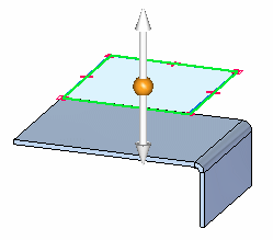
Position the cursor over the sketch region as shown, then click to select it.
Note:Depending on the current settings on your computer, the sketch region may highlight as a shaded element or only the edges may highlight.
Notice that a handle is displayed in the graphics window.
![]()
Select the Extrude handle and construct the feature
![]()
-
Position the cursor over the Extrude handle, as shown above, and when it highlights, click to select it.
A tab feature is constructed, and the sketch is automatically hidden.
![]()
Save the file
![]()
-
On the Quick Access toolbar, click the Save button
 to save the work you have done so far.
© 2021 UDS