Activity: Move a feature
Move a feature
In this activity we will move a feature and use the Selection Manager to select the feature.
Launch the Activity: Move a feature.
Rotate the view
-
Choose the View tab→Orient group→Rotate command
 .
. -
In the graphics window, click the Z rotation axis.
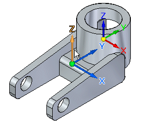
-
On the Rotate command bar, type -115, then press Enter.
The view rotates as shown below.
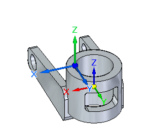
-
On the Rotate command bar, click the Close button.
Fit the view
![]()
-
On the View tab→Orient group, choose the Fit command
 .
.
Evaluate the next move operation
![]()
For the next move operation, move the rectangular cutout down along the Z axis, as shown above.
Explore options for selecting faces using Selection Manager.
Selection Manager Overview
![]()
In the next few steps, select the face shown highlighted in the illustration above, and then use Selection Manager to add more faces to the select set.
Selection Manager allows you to add elements to or remove elements from a select set based on the topological or attribute data of a currently selected focus element.
Selection Manager mode activates by choosing Home tab→Select group→Select list→Selection manager mode. You can also activate Selection Manager by pressing Shift+Spacebar. To end the Selection Manager mode, press the Spacebar.
Selection Manager is available when you select one or more model faces or features. Selection Manager contains menu items, similar to a shortcut menu.
Selection Manager Overview continued
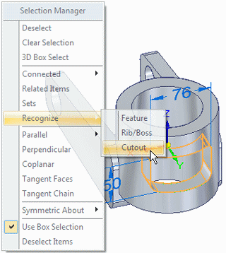
When in Selection Manager mode, selecting a face displays the Selection Manager menu, which allows you to add items to the current select set.
As you pass your cursor over the menu items in the Selection Manager menu, faces on the model that match the menu criteria highlight in the graphics window.
For example, you can use Selection Manager to select all the faces which are part of a cutout feature to which the currently selected face belongs.
Select a face
![]()
-
On the Home tab→Select group, choose the Select command
 .
. -
Position the cursor over the planar face at the approximate position shown, then click to select it.
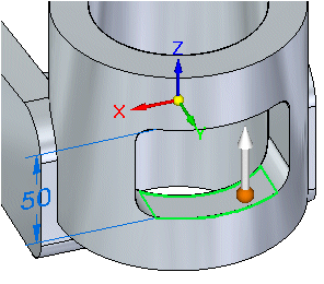
The steering wheel appears on the selected face.
Use Selection Manager to select additional faces
-
Start the Selection Manager mode by pressing Shift+Spacebar.
-
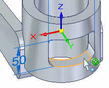
Click the face shown to display the Selection Manager menu.
-
Position the cursor over the title bar of the Selection Manager menu, then drag it to a location where you can see the entire face you selected, and as much of the model as possible.
-
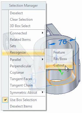
On the Selection manager menu, position the cursor over the Recognize→Cutout option, then click.
-
Press Spacebar to exit the Selection Manager mode.
Observe the results
![]()
Notice that the Recognize→Cutout selection manager option selects all faces of the cutout.
Select the vertical axis on the steering wheel
![]()
-
Position the cursor over the vertical axis on the steering wheel, then click to select it.
-
Move the cursor up and down vertically.
Notice that the entire cutout moves up and down vertically with the cursor and that a dynamic input box appears so that you can reposition the cutout precisely.
Move the cutout feature
-
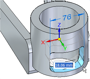
Position the cursor below the part such that the delta move distance is approximately 18 mm.
-
In the dynamic input box, type 18, then press Enter.
-
Move the cursor away from the part, then double-click the left mouse button quickly to clear the select set.
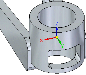
Your part should now appear as shown.
Rotate the view and save the part
![]()
-
Press the Ctrl+I keys to rotate the view to the isometric orientation.
-
On the Quick Access toolbar, choose the Save command
 .
.
© 2021 UDS