Activity: Modify the model
Modify the model
![]()
In this activity you will modify the model to lengthen the mounting arms and relocate the cylindrical cutouts, as shown.
While modifying the model, continue to explore the tools that are available for modifying model geometry.
Launch the Activity: Modify the model.
Select the cylindrical cutout
-
Position the cursor over the cylindrical face shown, then click to select it.

Several tools appear that you can use to evaluate and control how the model reacts to the modification:
-
Steering wheel
-
Command bar
-
Design Intent panel
In the next few steps, learn more about these tools.
Observe the on screen tools
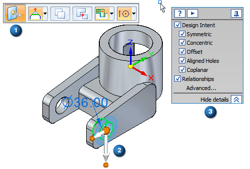
Notice the following:
-
A floating menu, called command bar (1), appears in the graphics window.
-
A 2D steering wheel (2) appears at the center point.
-
The Design Intent panel (3) appears.
Move the cylindrical cutout
-
Position the cursor over the primary axis on the steering wheel, and when it highlights, click to select it.
-
Move the cursor slowly to the right, then to the left.
Notice the following:
-
The concentric cylindrical face on the adjacent mounting arm also moves.
-
The preserved Design Intent relationships detect symmetry about the Base: (Y)Z plane. The symmetry option appears with a green icon.

-
When you move the cursor to the right, such that the cylindrical face extends into the interior of the part, an error symbol appears.
-
Synchronous editing in action
![]()
Options in the Advanced Design Intent panel appear in green when an active relationship matches a Design Intent setting.
In this example, the Symmetric about Base: (Y)Z setting ensures that, to preserve symmetry about the YZ plane of the base coordinate system, the non-selected cylindrical face also moves when the selected cylindrical face moves.
![]()
The error symbol appears because the cursor moves such that the cylindrical cutout would no longer modify the part.
![]()
Synchronous technology notifies you for this condition.
For this modification, you also want to lengthen the part, so this requires additional faces in the select set.
In the next few steps, add the planar end face on the right mounting arm to the select set.
Restart the move operation
![]()
-
Position the cursor in the graphics window, then right-click to restart the move operation.
Notice the following:
-
The cylindrical faces are returned to their original positions.
-
The full steering wheel reappears.
-
The Concentric and Symmetric about Base: (Y)Z options in the Advanced Design Intent panel return to an undetected state.
Steering wheel overview
The following explains some of the fundamental features of the steering wheel when moving faces in the direction of one of the steering wheel axes:
![]()
-
(1) Axis-Click to move elements along the three axes.
-
(2) Origin knob-Use to define the from point for from/to moves. You can also click/drag the origin knob to reposition the steering wheel to another location on the model. This allows you to redefine the axis directions in which you want to move the face set based on another edge of the model.
-
(3) Torus knobs-Click one of the four knobs to reorient the axes.
There are more features available with the steering wheel, but this provides you with the fundamentals.
Design Intent overview

Depending on the current configuration of your computer, the settings for Design Intent relationships to recognize on your computer may be different than the illustration.
-
On the Advanced Design Intent panel, click the Restore Defaults button
 .
.
Your Design Intent settings should now match the illustration.
Use the Design Intent options to locate and display the relationships between faces in the current select set and the rest of the model. Use this information to control how much of the design intent that is built into a synchronous is preserved or ignored during a move.
For example, when moving a planar face, the Design Intent relationships identify all the faces in the model that are coplanar to the face you are moving. Use the Design Intent options to specify whether any, some, or all of these coplanar faces move when the selected face moves.
The Design Intent panel is opened when you make the following types of synchronous modeling modifications:
-
Moving or rotating model faces or features in a synchronous part or assembly document.
-
Defining 3D geometric relationships between model faces using the Relate command in a synchronous part document.
-
Editing the dimensional value of a 3D PMI dimension in a synchronous part or assembly document.
The current Advanced Design Intent panel settings recognize the following design intent relationships, as shown above:
-
 Concentric faces remain concentric.
 -
 Coplanar faces remain coplanar.
 -
 Tangent edges remain tangent.
 -
 Maintain model symmetry about the base coordinate system.
Add the planar end face to the select set
-
Press and hold the Ctrl key down.
-
Position the cursor over the planar face shown, then click to select it.
Both the cylindrical face selected earlier and the planar face should now be selected.
Move the faces using the steering wheel
-
Position the cursor over the steering wheel axis shown in the illustration below, and when it highlights, click to select it.
-
Move the cursor slowly to the right, then to the left.
Notice the preserved symmetry, as shown in the Advanced Design Intent panel:
-
The position of both cylindrical faces and the length of both mounting arms change as you move the cursor.
-
The Symmetric About Base: (Y)Z option appears in the Advanced Design Intent panel as detected and preserved.
-
The delta move distance appears near the cursor.
-
Define the extent of the move operation
-
Position the cursor to the left such that the mounting arms are approximately 60 mm longer, as shown, then type 60, and press Enter to define the move distance.
The model updates as shown below.
![]()
Save the part
![]()
-
On the Quick Access toolbar, choose the Save command
 .
.
© 2021 UDS