Activity: Constructing a hole and adding rounds
Constructing a hole and adding rounds
In this activity you will learn how to define hole parameters, understand the hole command bar, construct a hole, understand the round command bar, and place rounds on a model.
Launch the Activity: Constructing a hole and adding rounds.
Prepare to construct a hole
![]()
In the next few steps, construct a hole feature.
-
Choose the Home tab→Solids group→Hole command
 .
.
Define the hole parameters
-
On the Hole command bar, click the Hole Options button. The Hole Options dialog box appears.

-
On the Hole Options dialog box, do the following:
-
Set the hole type to Simple
 .
. -
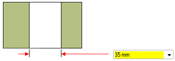
Set the Diameter to 35.
 Note:
Note:The yellow field indicates the hole size entered is not in the database for the selected hole type and standard.
-
Click OK.
-
Ensure the Center Point option on command bar is on
![]()
For this hole, you want the hole centered on the circular face of the boss.
-
On command bar, on the Keypoints list, choose the Center Point option
 .
.
Position the hole feature
-
Move the cursor over different faces of the model, and notice that a preview image of the results appear.
-
Position the cursor over the face shown in the illustration, but do not click.
-
Move the cursor to the circular edge as shown, and notice that the hole centers itself on the circular face.
-
Click to place the hole feature.
-
Notice that a hole feature is still attached to the cursor. Since this is the only hole you want to construct, right-click to finish placing holes.
![]()
Notice that a hole feature is attached to the cursor.
Observe the results
![]()
Notice that in addition to the hole feature, that the steering wheel (1) and the edit definition handle (2) appear.
Learn more about the steering wheel later.
Use the edit definition handle to edit procedural features, such as holes. For this tutorial, you will not edit the hole feature.
Save the part
![]()
-
On the Quick Access toolbar, choose the Save command
 .
.
Round selected part edges
![]()
In the next few steps, use the Round command to round four edges on the part.
-
Choose the Home tab→Solids group→Round command
 .
.
Select the first edge to round
-
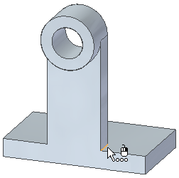
Select the edge shown.
-
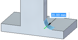
When the Dynamic Edit box displays, type 20, and then press Tab.
 Note:
Note:When rounding multiple edges, press the Tab key so you can continue to select more edges.
Select another edge to round and finish the feature
-
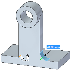
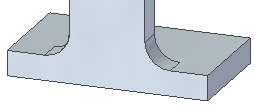
Select the edge shown.
-
Right-click to finish rounding edges.
Round two more edges
-
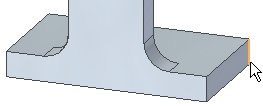
Select the edge shown.
-
Type 25, and then press Tab to specify the round size.
-
Select the edge shown, and then right-click to finish rounding edges.

The Round command is still active.
Observe the results
![]()
Your model should now resemble the illustration.
Save the part
![]()
-
On the Quick Access toolbar, choose the Save command
 .
.
© 2021 UDS