Activity: Constructing other extruded features
Constructing other extruded features
In this activity you will learn how to lock and unlock sketch planes, understand sketch shortcuts, add sketch relationships, and construct additional extruded features.
Launch the Activity: Constructing other extruded features.
Construct another extruded feature
![]()
In the next few steps, construct another extruded feature.
Use a workflow similar to the one used to construct the base feature.
First draw a sketch, and then extrude the sketch using the Select tool.
Evaluate the sketch
![]()
Draw the sketch for the next feature.
-
Lock cursor input to the front planar face on the model.
-
Use the Line command to draw the two lines and arc shown.
-
Place a dimension on the arc to control its size.
-
Use a geometric relationship to symmetrically center the sketch on the base feature.
Start the Line command
![]()
You can use the Line command to draw a series of connected lines and arcs.
-
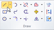
Choose the Home tab→Draw group→Line command
 .
.
Lock sketch input to a model face
-
Position the cursor over the planar face shown in the illustration.
Notice the following:
-
The planar face highlights.
-
A lock symbol appears adjacent to the cursor.

-
A Tooltip appears.
-
-
Press the F3 key to lock sketch input to the selected face.
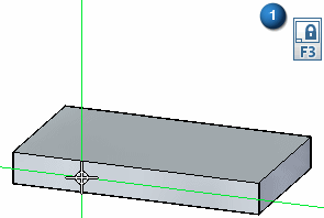
Notice that a locked plane icon (1) appears in the top- right corner of the graphics window.
Also notice that when you move the cursor over the other model faces, they no longer highlight. All sketch input is locked to the selected model face.
![]()
When drawing sketches, lock sketch input to a specific planar face on the model. This is useful when you want to draw outside the area defined by the planar face.
You can lock cursor input to the sketch plane using the lock symbol that appears adjacent to the cursor, or you can use a shortcut key.
Start the first line
-
Position the cursor as shown, and when the point-on relationship icon appears
 adjacent to the cursor, click to start the line.
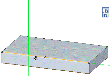
-
Move the cursor upward. Notice the following:
-
A line stretches to follow the cursor wherever you move it.
-
Line length and angle edit boxes are attached to the line.
-
When the line is vertical, a vertical relationship icon
 appears adjacent to the cursor.
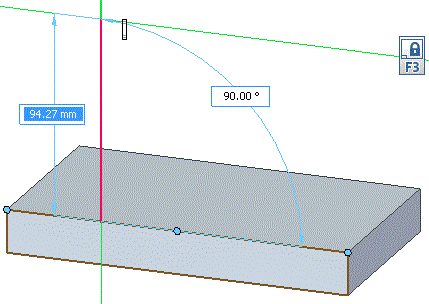
-
Finish the first line
-
Move the cursor until:
-
The vertical relationship indicator
 appears at the cursor.
 -
The Length displayed on the edit box is approximately 120 mm.
-
-
When the line is vertical, and approximately 120 mm, click to finish the first line.
![]()
Draw an arc tangent to the line
-
On the Line command bar, click the Arc option, or press A. This changes from line creation mode to arc creation mode.
Four quadrants (1) appear at the endpoint of the line you just drew. The arc is drawn perpendicularly or tangentially to the line, depending on which intent zone you move the cursor through.
Note:What is an intent zone?
A circle divided into four quadrants that allows you to specify how you want to draw an element. Intent zones appear when drawing a line that is connected to an arc or circle, or when drawing an arc connected to a line.
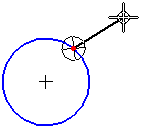
By moving the cursor through one of these intent zones on the way to your next click location, you can control whether the new element is tangent to, perpendicular to, or at some other orientation to the element it is connected to.
-
Move the cursor through the different intent zones and notice how the arc behaves.
-
On the arc edit box, type 30 as the radius of the arc, and press Enter.
-
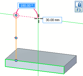
Move the cursor up, through the top quadrant of the intent zone, and then to the right, so that the arc curves tangentially to the right.
-
When a dotted horizontal line appears between the start and endpoints of the arc, as shown, click. You could also enter 180 in the angle edit box.
-
Click the button below to show a brief animation.
![]()
The Line command is still active, ready to draw another line connected to the endpoint of the previous line. In this case, you want to draw an arc instead.
Draw the second line
-
Position the cursor as shown, and when the point on element and tangent relationship icons appear adjacent to the cursor
 , click to finish the line.
-
When you finish drawing the line, right-click to restart the Line command.
The Line command is still active, ready to draw a line connected to the endpoint of the previous arc.
Observe the results
![]()
Take a few moments to observe the finished sketch.
Notice that the sketch elements form a closed area that is shaded blue. This indicates that the sketch is valid for constructing a feature using the Select tool. Although this sketch is not closed, it is treated as a sketch region because the linear model edge at the bottom of the sketch closes the gap between the two lines on the sketch.
Also notice the relationship symbols where the lines connect to the solid model, to the endpoints of the arc, and at the midpoint of lines.
These relationships specify the following:
-
The lines remain connected to the model, but can move to the right and left.
-
The lines remain connected and tangent to the arc.
-
The lines remain vertical.
Although the sketch and the relationships are discarded when you construct the next solid feature, building these relationships into the sketch is helpful. When you construct the solid feature, these 2D relationships orient the faces that are constructed from the sketch, and help define the behavior you want when editing the solid feature later.
Unlock the sketch plane
![]()
Since you are finished drawing sketch elements, unlock the sketch plane.
-
With your cursor in the QY CAD window, click the lock icon
 to unlock the sketch plane.
Fit the view
![]()
Commands for adjusting the contents of the graphics window are located at the bottom-right side of the QY CAD application window.
-
Choose the Fit command
 to fit the contents of the view to the graphics window.
Place a sketch dimension and a geometric relationship
![]()
In the next few steps, place a 2D sketch dimension and a geometric relationship to control the size and position of the sketch.
-
Choose the Home tab→Dimension group→Smart Dimension command
 .
.
Dimension the arc
-
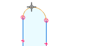
Position the cursor over the arc, and select it. Notice that dimension elements attach to the cursor.
-
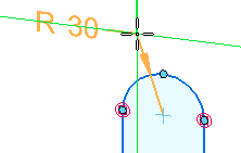
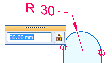
Position the cursor above the sketch. Click to position the dimension. The dimension edit value box appears near the dimension.
-
Do one of the following:
-
If the dimension value is 30 mm, right-click to accept the value.
-
If the dimension value is not 30 mm, type 30 in the Dimension Edit box, then press Enter.
-
Place a horizontal/vertical sketch relationship
![]()
In the next few steps, apply a vertical relationship (1) between the arc on the sketch and the midpoint of an edge on the base feature created earlier. This relationship orients the sketch on the center of the base feature.
This technique also ensures the sketch symmetrically aligns with respect to the base coordinate system, because the base feature is symmetrically aligned to the base coordinate system.
-
On the Home tab→Relate group, choose the Horizontal/Vertical command
 .
.
Select the center of the arc
-
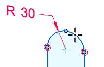
Position the cursor over the arc, but do not click.
-
Move the cursor to the approximate center of the arc, and notice that a center point icon appears adjacent to the cursor
 .
.
-
While the center point icon appears, click.
Select the midpoint of the model edge
-
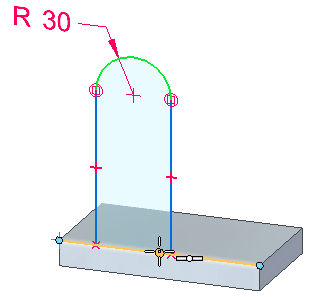
Position the cursor over the midpoint of the model edge. When the midpoint relationship icon appears adjacent to the cursor
 , click to finish defining the vertical relationship.
Observe the results
![]()
Notice that the sketch centers about the base feature, and that a vertical relationship symbol appears (1) between the center of the arc and the edge of the base feature you selected.
Start the Select command and select the sketch region
-
Choose the Select command
 .
. -
Position the cursor over the sketch region, and when it highlights, click.
The Extrude handle and command bar appear.

![]()
Select the Extrude handle and define the feature extent
-
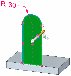
Position the cursor over the Extrude handle. When it highlights, click.
-
Position the cursor behind the sketch and notice that the feature draws dynamically as you move the cursor.
-
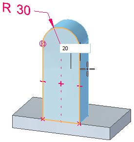
In the dynamic input box, type 20, then press Enter to define the extent for the feature.
Hide the dimensions and save the part
-
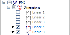
Use PathFinder to hide the radial and linear dimensions in the PMI collector.
-
On the Quick Access toolbar, choose the Save command
 .
.
![]()
Again, the 2D sketch dimension placed is migrated as a 3D PMI dimension when you construct the feature. Also an extent PMI dimension is created.
Construct another extruded feature
![]()
In the next few steps, sketch a circle, and then use the sketch circle to construct a boss on the part.
Start the Circle by Center Point command
-
Choose the Home tab→Draw group→Circle by Center Point command
 .
.
Lock sketch input to a model face
-
Position the cursor over the planar face. When it highlights, press F3 to lock sketch input to the selected face.
As before, notice that the locked plane icon appears.
![]()
Define the center of the circle
-
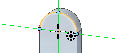
Position the cursor over the arc-shaped edge of the model, but do not click.

-
Move the cursor to the approximate center of the arc-shaped edge, and notice that a center point icon appears adjacent to the cursor
 .
.
-
While the center point icon appears, click to place the circle centered on the arc center point.
Define the diameter of the circle
-
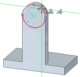
Position the cursor over the arc-shaped edge of the model, and when the point-on and tangent-to indicators appear
 , click to define the diameter of the circle.
Unlock the sketch plane
-
Click the plane lock icon to unlock the sketch plane.
![]()
Start the Select command
Use the Select tool to construct another extrude feature.
-
Choose the Select command
 .
.
![]()
Select the sketch region
-
Position the cursor over the circle, and when the sketch region highlights, click.
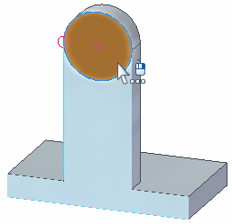
Command bar and the Extrude handle appear.
![]()
Select the Extrude handle
-
Position the cursor over the Extrude handle, and click.
![]()
Set the feature extent and direction
-
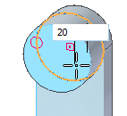
Move the cursor in front of the model.
-
In the dynamic input box, type 20, then press Enter.
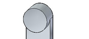
The feature is constructed.
-
Hide the dimension.
Observe the results
![]()
Your extrude feature should resemble the illustration.
Save the part
![]()
-
On the Quick Access toolbar, choose the Save command
 .
.
© 2021 UDS