Activity: Synchronous editing
Synchronous editing
In this activity you will learn how to place a PMI dimension, edit a PMI dimension, gain knowledge of the Design Intent panel, control a dimension’s edit direction, and understand how to use the steering wheel to make synchronous edits.
Launch the Activity: Synchronous editing.
Display the base coordinate system
In the next few steps, learn about some of the methods you can use to edit models in the QY CAD synchronous environment. One of these editing tools evaluates the position of the model relative to the base coordinate system.
-
In PathFinder, position the cursor over the check box for the Base entry, then click to display the Base coordinate system in the graphics window.
The Base coordinate system appears.
![]()
Prepare to place a PMI dimension on model edges
![]()
In the next few steps, place a dimension between the bottom edge of the model, and the center of the hole constructed earlier. These types of dimensions are called 3D, or PMI dimensions.
Earlier, when you placed 2D dimensions on the sketches, then constructed solid features, the 2D dimensions were converted to PMI dimensions.
You can also place PMI dimensions directly by dimensioning edges on the solid model.
Use these dimensions for reference purposes, or you can use them to drive changes to the model.
-
Choose the Smart Dimension command
 .
.
Select the first element to dimension
-
Position the cursor over the bottom edge of the model, and when the edge highlights, click.
-
Do not click to place the dimension. Select the second element in the next step.
Although dimension elements are attached to the cursor, this time you want to place a dimension that measures the distance between two elements.
![]()
Earlier, you used this command to place a dimension on one element. You can also use Smart Dimension to place a dimension between two elements.
Select the second element to dimension
-
Position the cursor over the circular edge of the hole. Click when the center point highlights.
Position the dimension
-
Position the cursor to the left of the model, and click to place the dimension.
The dimension is placed as shown and is available for a dimension change. The face that is affected by a change also highlights in blue.
-
Press Enter to accept the current value.
![]()
Pass the cursor over the dimension components
-
Choose the Select command
 .
. -
Position the cursor over the dimension line, but do not click.
Notice that the cursor changes to indicate that you can change the dimension position if you click the dimension.
-
Slowly move the cursor down, until it touches the top of the dimension value text.
Notice that the cursor and top dimension line arrowhead change. These changes indicate that you can change the dimension value and the model will change size upward if you click the dimension.
Continue observing dimension display changes
-
Move the cursor slowly up and down over the dimension text and notice that the bottom dimension line arrow changes when the cursor is near the bottom of the dimension value text. These changes indicate that you can change the dimension value and the model will change size downward if you click the dimension.
-
Continue moving the cursor slowly over the various dimension components and observe the display changes that occur as you move the cursor.
These display changes indicate what actions are possible when you click at specific positions on the dimension.
Select the dimension to edit
-
Position the cursor over the dimension text. When the dimension text highlights, click.
When you select the dimension, several editing tools appear, and the display of the model updates. In the next few steps, learn more about these tools.
The Dimension Value Input box and Modify command display.
![]()
Observe the on-screen tools
![]()
Notice the following:
-
(1) Modify command bar appears in window.
-
(2) The cylindrical model face that the dimension refers to changes color.
-
(3) The Dimension Value Input box appears near the dimension text.
-
(4) The Design Intent panel appears.
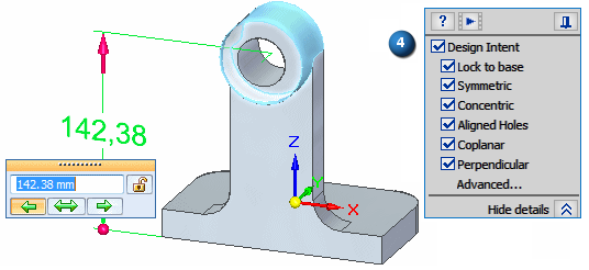
Dimension Value Input overview
![]()
Take a few moments to observe the options on the Dimension Value Input dialog box and the display of the selected dimension.
-
(1) Edit Direction 1 - Specifies that the model geometry moves from this end when set. Notice that for this dimension, this option is set and the dimension has a large arrow at this end. If you change the dimension value, this end of the model changes.
-
(2) Symmetric Dimension- Specifies that the model geometry move an equal distance from the dimension center.
-
(3) Edit Direction 2 - Specifies that the model geometry moves from this end when set. Notice that for this dimension, this option is cleared and the dimension has a dot at this end. If you change the dimension value, this end of the model remains stationary.
-
(4) Locked/Unlocked - Specifies whether the model geometry controlled by the dimension can change when making modifications with the steering wheel, or whether it must remained locked. Notice that for this dimension, this option is set to Unlocked.
-
(5) Dimension Value box - Specifies a precision value for the dimension. Use this box to type new dimension values when editing models.
Design Intent overview
-
Click the Advanced... option in the Design Intent panel to open the Advanced Design Intent panel.
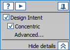
Depending on the current configuration of your computer, the active Design Intent settings on your computer may be different than the illustration.
-
On the Advanced Design Intent panel, click the Restore Defaults button
 .
.The Design Intent settings should now match the illustration.
For this edit, the following relationships are found and are maintained when you edit the dimension value.
-
(1) Concentric: The outside cylindrical face of the boss is concentric to the hole cylinder.
-
(2) Tangent: The planar faces which are tangent to the outside cylindrical face on the boss.
-
Use the Design Intent options to locate and show the relationships between faces in the current select set and the rest of the model. Use this information to control how synchronous modifications are performed.
The Design Intent panel opens when you make the following types of synchronous modeling modifications:
-
Moving or rotating model faces.
-
Defining 3D geometric relationships between model faces using the Relate command.
-
Editing the dimensional value of a 3D PMI dimension.
When a indicator in the Advanced Design Intent panel is turned off![]() , the associated design intent relationship is not maintained during an edit.
, the associated design intent relationship is not maintained during an edit.
An indicator with an orange shade  is turned on. This indicates the associated design intent relationship is maintained during an edit.
A green shaded option ![]() indicates the associated relationship is detected for this edit.
indicates the associated relationship is detected for this edit.
A red shaded option  indicates the model relationship is found but has been suppressed.
Set the edit direction and type a new dimension value
-
Ensure the Edit Direction is set as shown.
-
Type 150 and press Enter.
![]()
On the Dimension Value Input dialog box, do the following:
Observe the results
![]()
Notice that the hole position changes in response to the dimension value edit. Also noticed that the boss remains concentric to the hole, and the tangency is also maintained.
Hide the dimension
-
Use PathFinder to hide the dimension you just edited.
Your model should display as shown below.
![]()
Modify the model using the steering wheel
-
Choose the Select command
. -
Position the cursor over the face shown above. When it highlights, click.
Notice that command bar (1) and a steering wheel handle (2) appear. Also notice that the 160 mm dimension appears.
In the next few steps, you will edit the model using the Select tool and the steering wheel.
You use the steering wheel to interact directly with the faces on the model.
Steering wheel overview
When you select a face on a model, the default action is to move the face. You can specify other options, but for this tutorial, focus on the Move option.
![]()
The steering wheel allows you to manipulate model faces, such as to move or rotate one face, or a set of faces.
You can use the different controls on the steering wheel to control the manipulation process.
By default, only the primary axis and origin knob on the steering wheel appear when you select a face.
![]()
The following explains some of the fundamental features of the steering wheel:
-
(1) Axis - Click to move elements along the axis.
-
(2) Reposition primary axis knobs - Click one of the four knobs to reposition the primary axis in the selected direction.
-
(3) Torus - Click to rotate elements about the current primary axis.
-
(4) Origin knob - Use to define the from point for from/to moves. You can also click/drag the origin knob to show all the steering wheel options and to reposition the steering wheel to another location on the model. This allows you to redefine the axis directions in which you want to move the select set based on another edge of the model, for example.
There are more features available with the steering wheel, but this provides you with the fundamentals.
Modify the model using the primary axis on the steering wheel
-
Position the cursor over the primary axis on the steering wheel, and when it highlights, click.
-
Move the cursor to the right and left.
Notice the following:
-
The adjacent faces of the model update as you move the face.
-
The dimension value of the PMI dimension updates.
-
A symbol appears in the graphics window to indicate that the value of the PMI dimension is changing.
-
Advanced Design Intent panel updates to indicate that the model is symmetric about the (Y)Z axis of the base coordinate system.
-
The dynamic input box appears near the cursor so you can type a precise value for the delta distance of the move.
-
-
Position the cursor such that the value of the PMI dimension is less than 160 mm, type 5, and then press Enter.
Observe the results
![]()
Take a few moments to observe the results of the edit.
Notice that the value of the PMI dimension is now 150 mm. Because the model is symmetric about the (Y)Z axis of the Base coordinate system, both the selected face, and its matching face on the other side of the model move 5 mm.
Save the part
-
On the Quick Access toolbar, choose the Save command
 .
. -
Close the file.
![]()
© 2021 UDS