Constructing a synchronous base feature
Constructing a synchronous base feature
In this activity you will learn how to sketch and dimension profiles, take advantage of part symmetric edit dimensions, understand sketch regions, utilize extrude handles and gain knowledge of PathFinder.
Launch the Constructing a synchronous base feature.
Open the activity part file
-
Open ...\Program Files\UDS\QY CAD 2022\Training\stppabg.par.
-
Click the Application button
 .
. -
On the Application menu, choose the Save As→Save As command.
-
On the Save As dialog box, save the part file to a new name or location so that other users can complete this activity.
Synchronous part modeling workflow overview
![]()
You model synchronous features using the following basic workflow:
-
Draw a sketch for the first feature.
-
Add dimensions to the sketch.
-
Extrude or revolve the sketch into a solid feature.
-
Add more features.
-
Edit the model dimensions and solid geometry to complete the part.
As you work through this tutorial, you learn more about the concepts listed above.
Modeling environment
QY CAD part and sheet metal files have two modeling environments available for creating features. The environments are called synchronous and ordered.
You control the environment that new files open in by setting an option on the Helpers page in QY CAD Options. The default setting opens a new file in the synchronous environment.
Existing files that contain ordered features or both ordered and synchronous features open in the ordered environment.
Existing files that contain only synchronous features open in the synchronous environment.
The active part file stppabg.par opens in the synchronous environment because it was saved in that environment.
Observe the base coordinate system
![]()
The first step in drawing any new part is drawing the sketch for the base feature. The first sketch defines the basic part shape.
Draw a sketch on one of the principal planes on the base coordinate system, and then extrude the sketch into a solid.
What is the base coordinate system for?
The base coordinate system is located at the origin of the model file, as shown above. It defines the principal x, y, and z planes, and can be used in drawing any sketch-based feature.
Depending on the configuration of your computer, there may also be a view orientation triad (2) displayed in the graphics window. If so, the base coordinate system (1) is the element shown highlighted in the illustration below. The view orientation triad, which cannot be selected, is for view orientation purposes only. For the remainder of this tutorial, the view orientation triad is not shown.

Start the Rectangle by Center command
![]()
Draw and dimension the rectangle shown.
-
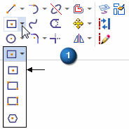
On the Home tab→Draw group (1), click the Rectangle list. Choose the Rectangle by Center command
 .
.
Specify the sketch plane using QuickPick
-
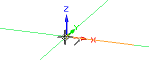
Position the cursor over the base coordinate system as shown. Hover a moment and notice that the cursor image changes
 to indicate that multiple selections are available.
 -
Right-click, and the QuickPick tool appears.

-
Move the cursor over the different entries in QuickPick, and notice that different principal planes on the coordinate system highlight in the graphics window. Using QuickPick, you select what you want when multiple selections are available.

-
Position the cursor over the entry in QuickPick that highlights the XY principal plane, and then click to select it.
Observe the alignment lines attached to the cursor
![]()
-
Move the cursor around the graphics window and notice that alignment lines extend outward from the cursor.
The alignment lines orient to the principal plane selected in the previous step.
Draw a rectangle
-
Position the cursor at the origin point of the base coordinate system, and when the endpoint relationship indicator
 appears adjacent to the cursor, click to define the center point of the rectangle.
-
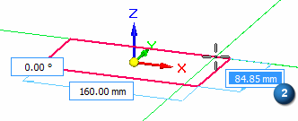
Move your cursor to the right, and notice that the Width, Height, and Angle edit boxes attach to the dynamic rectangle to reflect the current cursor position.

-
Type 160 in the Width edit box (1), and then press Enter. This locks the rectangle width to 160 mm.
-
Position the cursor approximately as shown, and when the Height value (2) for the rectangle is between 80 and 90 mm, click to place the rectangle.
Observe the rectangle

Take a few moments to observe the rectangle. You draw 2D elements by entering a value in the dynamic edit boxes, or use the cursor to define an approximate size in the graphics window.
If the rectangle displays red icons on each sketch element, it is because the relationship handles display is on. To turn off the display, choose Sketching tab→Relate group→Relationship Handles command ![]() .
.

In the next few steps, you place and edit dimensions to define both the width and height of the rectangle.
Take a few moments to also observe that the rectangle appears as a shaded element.
In the QY CAD: synchronous environment, when 2D elements form a closed area, they are referred to as sketch regions. Regions are helper objects that make it easier to construct surface and solid geometry from sketch elements, or a combination of sketch elements and model edges. Regions are created by QY CAD when a series of sketch elements or model edges form a closed area. Use sketch regions to create solid features. Regions appear using a shaded color.
Depending on the current settings on your computer, the sketch region may not appear as a shaded element.
Dimension the rectangle width
-
On the Home tab→Dimension group, choose the Smart Dimension command
 .
. -
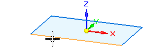
Position the cursor over the bottom horizontal line on the rectangle. When the line highlights, click to select it.
-
Move the cursor off the sketch, then click to define the dimension location.
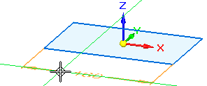
-
Notice that a dimension value edit box appears in the graphics window.
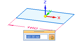
-
Do one of the following:
-
If the dimension value is 160 mm, right-click to accept the value.
-
If the dimension value is not 160 mm, type 160, then press Enter.
-
Dimension lock
![]()
When placing a dimension, the dimension value locks by default. A locked dimension means that the dimension is a driving dimension. Driving dimensions are red. Unlocked or driven dimensions are blue. You can edit a locked dimension, but you cannot edit an unlocked dimension.
On the Dimension Edit box, click the lock to switch between locked ![]() or unlocked
or unlocked ![]() dimension values.
dimension values.
The importance of the dimensional lock is shown when the base feature is created in an upcoming step.
Dimension the rectangle height
-
Position the cursor over the vertical line on the left side of the rectangle. When the line highlights, click to select it.
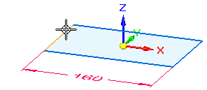
-
Move the cursor to the left, then click to position the dimension.
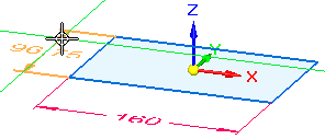
-
In the dimension value edit box, type 90, then press Enter.
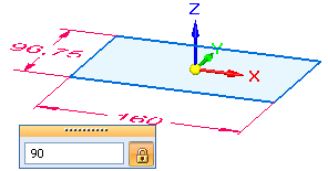
The Smart Dimension command ![]() is still active.
is still active.
Rotate the view and display the relationship handles
-
Change the view to a top orientation by pressing Ctrl + T.
-
Choose the Sketching tab→Relate group→Relationship Handles command
 .
.
-
This command turns on the display of the 2D relationship handles for sketches.
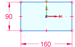
Observe the sketch
![]()
| Notice that symbols representing geometric relationships appear on the rectangle. |
Geometric relationships control how the sketch geometry reacts to modifications.
These relationships are automatically applied based on the cursor position and the current IntelliSketch settings. Learn more about this in the next few steps.
| The symbols on the midpoint of the lines represent horizontal (1) and vertical relationships (2). | |
| The symbols on the endpoints of the lines represent endpoint connect relationships (3). | |
| Horizontal and vertical relationships also appear between the origin of the base coordinate system and the midpoint of one of the horizontal and vertical lines, as shown (4) (5). These relationships are partially obstructed by the display of the base coordinate system, which is hidden in the illustration below. (Learn how to hide the base coordinate system later.) |
![]()
When you modify the rectangular sketch, the lines that make up the rectangle remain endpoint connected, horizontal and vertical, and symmetrically centered about the origin of the base coordinate system.
Taking advantage of part symmetry
![]()
Because the part you are constructing has symmetric features, you can take advantage of the part symmetry if you ensure that you draw the sketch for the first feature symmetric with respect to the base coordinate system.
The Rectangle by Center command automatically creates the vertical (4) and horizontal (5) relationships required to keep the rectangle symmetrically aligned about the origin of the base coordinate system.
There are also separate commands you can use to apply these relationships manually in other situations.
You can use the base coordinate system to take advantage of part symmetry and make your models easier to build and edit. This also helps build stability and predictability into your models.
Edit the dimensions
-
Press the Escape key to start the Select command.

You can also click the command on the Home tab→Select group, as well as several other tabs. However, pressing the Escape key is usually the quickest way to start the command.
-
Position the cursor over the 160 mm dimension, and click to select it. The Dimension Edit value box appears in the graphics window.
-
In the dimension value edit box, type 120, and then press Enter. Notice that the rectangle changes size, but remains symmetrically centered about the base coordinate system.
-
Experiment with other values for both dimensions to see the results. If you have a mouse with a scroll wheel, you can also edit a selected dimension by rotating the scroll wheel.
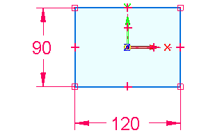
![]()
For this sketch, if you edit either of the dimensions, it remains symmetrically aligned about the origin of the base coordinate system.
Finish editing the sketch
-
Edit the dimensions so that they match the illustration.
-
Press Ctrl+J to change to a dimetric view orientation.
Your view should now display as shown in the illustration below.
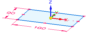
![]()
Prepare to construct the base feature
![]()
In the next few steps, construct the base feature using the sketch you drew.
In the QY CAD synchronous environment, you can construct solid geometry using two basic approaches:
-
Use a robust set of feature modeling commands such as extrude, revolved protrusion, and hole to construct specific types of features.
-
Use the Select tool to construct the most frequently used types of features: extruded and revolved protrusions and cutouts.
Both approaches produce the same results. You use both methods in this tutorial. As you gain experience, feel free to use the approach that is more comfortable for you.
To construct the base feature, use the Select tool. Using the Select tool reduces the number of steps required to construct these frequently used features.
Start the Select command and select the sketch region
-
Press the Escape key to start the Select command
 .
. -
Position the cursor over the sketch region, then click to select it.
 Note:
Note:Depending on the current settings on your computer, the sketch region may highlight as a shaded element or only the edges may highlight.
In the next few steps, learn about the on-screen tools that appear when you select the sketch.
Observe the on-screen tools

Notice the following, as shown in the illustration:
-
A command bar (1) displays in the graphics window, either vertically, as shown on the left, or horizontally, as shown above. The appearance of the command bar depends on the user interface theme you use. Our instructions use the horizontal representation of the command bar, because it is smaller and easier to display; but the two versions of the command bar always contain the same information and the same options.
-
An Extrude handle (2) appears on the sketch region, near where you selected it.
The Extrude command bar contains the available options for the current action.
Use the extrude handle to construct the feature. Before you construct the feature, you will learn more about command bar.
Command bar overview
![]()
Command bar appears when you select certain types of elements. Command bar evaluates the selected elements and presents a targeted set of Actions and Options.
Actions:
The Actions list appears on the left side of command bar (1).
For a sketch region, the default action constructs an extruded feature. You can select a different action from the Actions list. For a sketch region, you can also specify that you want to construct a revolved feature.
Options:
The options available for the current action appear on the remainder of command bar (2).
For an extruded feature you specify whether material is added or removed, the feature extent, whether the feature is constructed symmetrically about the sketch region.
Explore some of these options as you work through the tutorial.
Ensure the proper options are set on command bar
-
On command bar, set the following options:

-
(1) Extent Type (Finite).
-
(2) Symmetric Extent cleared (not set).
-
Select the Extrude handle and define the base feature extent
-
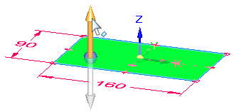
Position the cursor over the extrude handle, and when it highlights, click.
-
Move the cursor above and below the sketch and notice that the feature draws dynamically as you move the cursor.
Also notice that a Dynamic Edit box appears in the graphics window.
-
Position the cursor below the sketch, type 20 in the Dynamic Edit box, and then press Enter to define the extent for the feature.
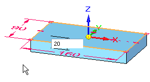
The base feature creation is complete.
Observe the results
![]()
Your graphics window should resemble the illustration.
-
Notice that a solid base feature appears and that the sketch no longer appears.
-
Notice that the 2D sketch dimensions are applied as driven to the base feature.
-
Notice that a driven PMI dimension is added for the 20 mm extent length.
When you construct sketch-based features in the QY CAD synchronous environment, the sketches are automatically hidden when you construct a feature, and any 2D dimensions you place on the sketch automatically convert to 3D PMI dimensions and attach to the appropriate model edges.
This process is called sketch consumption and dimension migration. Sketch consumption and dimension migration are discussed in detail in the Help delivered with QY CAD.
After you construct a synchronous feature, the original sketch geometry does not drive the feature. However the sketch dimensions are included to control the feature. All sketch dimensions are added to part edges as unlocked.
The cross section shape of the feature is locked. Only the face features that define the depth can be changed during a synchronous feature edit. To perform a synchronous face edit that affects the cross section, you can either delete the PMI dimension or unlock the dimension.
Explore PathFinder
-
Click the
 symbols in PathFinder to expand the various collectors until your display matches the illustration.
 -
Notice the following in PathFinder:
-
A PMI collector that contains entries for the PMI dimensions.
-
A Features collector that contains a Protrusion 1 entry, which represents the base feature you constructed.
-
A Used Sketches collector that contains a Sketch entry for the sketch you used to construct the feature.
When you construct sketch-based features, the sketches are added to the Used Sketches collector in PathFinder in case you want to restore them for subsequent features later.
-

Take a few moments to explore PathFinder.
Use PathFinder to help you evaluate, select, and edit the components that comprise the models you create in QY CAD.
Hide the base coordinate system and PMI dimensions using PathFinder
-
In PathFinder, position the cursor over the check box adjacent to the Base entry, and then click to clear the check box.

Notice that the Base entry in PathFinder changes font color and that the Base coordinate system no longer appears in the graphics window.

-
In PathFinder, clear the check boxes adjacent to the three dimension entries to hide the dimensions in the graphics window.

Save the part
![]()
-
On the Quick Access toolbar, located at the top-left side of the application window, choose the Save command
 .
.
© 2021 UDS