Activity: Select drawing views to create the 3D model
Select drawing views to create a 3D model
This activity:
-
Examines the Create 3D dialog box
-
Selects drawing views that you will use to create a 3D model
Launch the Activity: Select drawing views to create the 3D model.
Open the draft file
-
Open ...\Program Files\UDS\QY CAD 2022\Training\stddb3d.dft.
-
On the Application menu, choose Save As→Save As to save the document as a personal copy.
-
On the Save As dialog box, save the file to a new name or location so that other users can complete this activity.
Start the Create 3D command
-
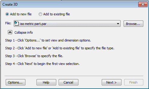
Choose the Tools→Assistants→Create 3D command
 .
.
-
In the Create 3D dialog box, ensure the File option is set to iso metric part.par.
-
Click the Options button.
-
In the Create 3D Options dialog box, do the following:
-
Verify that the Projection Angle option is set to Third.
Note:This tutorial illustrates third angle projection.
If you are more comfortable with first-angle projection, click First. If you choose to use first-angle projection for this tutorial, the orientation of the sketches in the Part document will not be the same as what the tutorial shows.
-
Verify that the Include Dimensions options for Linear and Radial are selected.
Click OK.
Click Next and leave the dialog box open.
After you define the information on the dialog box, you are ready to select the geometry to create the sketches. You can include lines, arcs, curves, and polylines as well as line strings created with imported data.
-
Select elements to define the primary view
![]()
-
Position the cursor above and to the left of the principal view, as shown above at (A), then press and drag the cursor below and to the right of the view, as shown at (B).
The drawing view geometry highlights as shown below. If your selected elements do not match the illustration below, you can select the elements again.
![]()
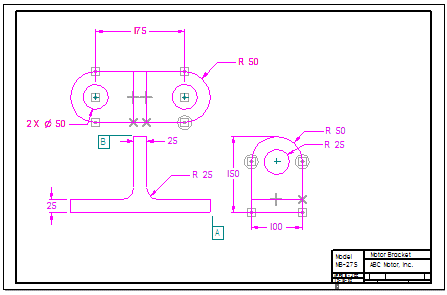
Select the elements for the next view
-
On the Create 3D dialog box, click the Next button.
-
Position the cursor above and to the left of the drawing view, as shown, then press and drag the cursor below and to the right of the view.
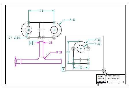
Be sure to define the area large enough to include all the dimensions in this drawing view.
Your drawing view should highlight as shown.
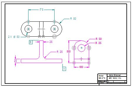
Select the elements for the next view
-
On the Create 3D dialog box, click the Next button.
-
Position the cursor above and to the left of the drawing view shown, then press and drag the cursor below and to the right of the drawing view.
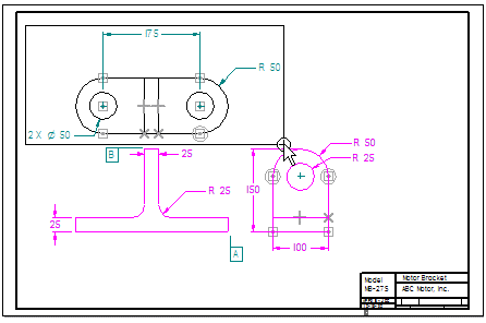
Your drawing view should highlight as shown.
Finish defining the views
-
On the Create 3D dialog box, click the
 button.
A new part document is opened, and the drawing view geometry is used to create sketches in the part document, as shown.
![]()
In the next activity you will use the sketches to create 3D solid geometry.
© 2021 UDS