Activity: Place the support part
Place the support part
This activity:
-
Uses a variety of relationships to fully position a part
-
Examines the Place Part command bar
-
Reviews the part placement options
-
Uses PathFinder to review assembly relationships
Launch the Activity: Place the support part.
Part Positioning Overview
![]()
To position parts in an assembly, apply a variety of assembly relationships.
For the support part, apply the following relationships to fully position the support part with respect to the base plate part:
-
Mate
-
Planar align
-
Axial Align
QY CAD provides a tool called FlashFit to apply each of these relationships, without having to specify the exact relationship type to use.
In the next few steps, use FlashFit to fully position the support as shown above.
Open the assembly file
-
Open the assembly saved in the previous activity, if it is not already open.
Place the support part
![]()
-
Click the Parts Library tab
 .
. -
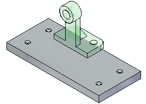
In the file list area on the Parts Library tab, select the file named support1.par, hold down the left mouse button, drag the file into the graphics window, and then release the mouse button at the approximate position shown in the top illustration.
The support part is placed into the assembly at the approximate position where the mouse button is released, as shown in the bottom illustration.
Review the part placement options
-
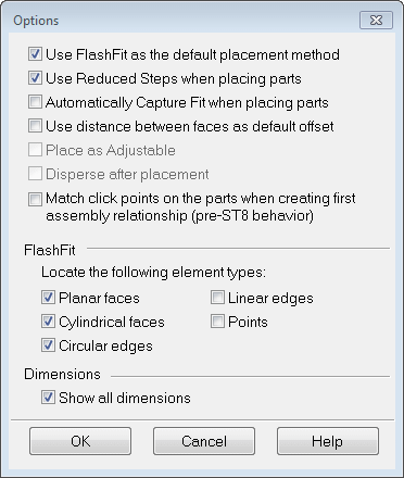
On the Assemble command bar, click the Options button
 .
. -
On the Options dialog box, ensure that the options match the illustration.
Notice that the FlashFit option specifies what types of faces FlashFit recognizes.
For this tutorial, and most part positioning scenarios, the FlashFit settings shown work well.
Mate the support to the base plate
![]()
When selecting faces for the first assembly relationship, QY CAD repositions the part being placed based on the approximate positions on the faces selected on the placement part and the part in the assembly.
The first relationship uses FlashFit to apply a mate relationship.
A mate relationship positions a part by orienting two planar faces so that they face each other.
Mated faces can touch or be offset from each other. For this part, the default offset value of zero, where the parts touch, is the appropriate option.
-
In the Relationship Types list, the FlashFit option should be active.

Use QuickPick to select the planar face on the support
![]()
Depending on the current computer settings, a tooltip may display adjacent to the cursor, as shown above. The Helpers page on the QY CAD Options dialog box, available on the Application menu→Settings, specifies whether a tooltip displays.
-
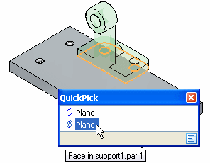
Position the cursor over the face shown highlighted in the top illustration, stop moving the mouse for a moment, and notice that the cursor image changes to indicate that multiple selections are available. Also notice that the cursor image indicates which button you must click to display the QuickPick list. The default is to right-click to display QuickPick.

-
Right-click, and QuickPick list displays. Move the cursor over the different entries in QuickPick, and notice that different elements of the model highlight. Use QuickPick to select the correct the element, the first time, without having to reject unwanted elements.
-
Use QuickPick to highlight the planar face shown below, and then left-click to select it.
Select the mating face of the base plate part
![]()
If the QuickPick cursor displays, but the proper face is highlighted, bypass QuickPick by left-clicking.
-
Select the top face on the base plate, as shown.
Observe the result
![]()
The mate relationship repositions the support part in the assembly.
Because only one assembly relationship is applied, the position of the support part might be slightly different than the illustration.
Prepare to align the support and the base plate
![]()
In the next few steps, apply a planar align relationship to reposition the support part approximately as shown in the illustration.
A planar align relationship aligns two planar faces such that they both face the same direction.
For this part, align the two faces on the support and base plate parts, as shown. These faces should not be coplanar: they will be parallel, but offset from one another.
Rather than specifying a specific offset distance, use a floating offset.
When the Floating Offset option is set, the offset value is determined by other relationships applied later. In this case, apply an axial align relationship later to control the offset value after applying the planar align relationship.
Select the aligning face on the support
![]()
-
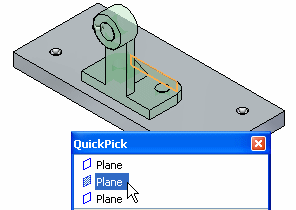
Position the cursor over the face shown, and wait for the QuickPick cursor to display.
-
Right-click, then use QuickPick to select the planar face on the support shown.
Specify a floating offset
![]()
-
Click the Floating Offset button.
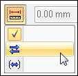
This setting allows the faces being aligned to take on whatever offset value is appropriate to satisfy the axial align relationship applied later.
Select the aligning face on the part in the assembly
![]()
-
Select the planar face on the base plate shown.
Note:Remember QuickPick can be bypassed when the proper face highlights.
Observe the result and flip the support
![]()
When positioning parts, FlashFit positioning logic analyzes the relative position of the faces selected to determine whether to apply a planar align or a mate relationship.
FlashFit applies the relationship that requires less part rotation. In this case, a mate relationship was the nearest solution.
For this part, a planar align relationship is required.
-
Click the Flip button to change the mate relationship to a planar align relationship.

The part is repositioned approximately as shown in the bottom illustration.
![]()
Axially align the support part with the base plate
![]()
In the next few steps, use FlashFit to apply an axial align relationship between a bolt hole on the support with a bolt hole on the base plate, as shown in the illustration.
The axial align relationship will fully position the support with respect to the base plate.
Select the cylindrical axis to align
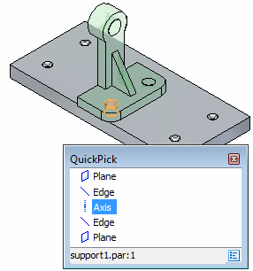
-
Use QuickPick to select the cylindrical axis shown in the illustration.
Align this cylindrical axis with the cylindrical axis on the base plate.
Select the cylindrical face on the base plate part
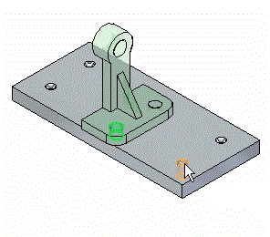
-
Select the cylindrical axis on the base plate part as shown.
Observe the result
![]()
The support part is now fully positioned in the assembly.
Notice that the Assemble command bar is dismissed.
Fit the window
![]()
Commands for adjusting the contents of the graphics window are located at the bottom-right side of the QY CAD application window.
![]()
-
Choose Fit to fit the contents of the view to the graphics window
 .
.
Use PathFinder to review the assembly relationships

-
In the top pane of PathFinder, click the support.par:1 entry, as shown above.
Notice that the relationships you applied display in the bottom pane of PathFinder, as shown below.

-
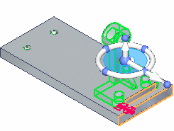
Pass the cursor over each of the relationship listings, but do not click.
Notice in the assembly window, that the faces used to apply the relationships highlight, as shown below.
Later, learn how to edit an assembly relationship.
Save the assembly
![]()
-
Choose Save
 .
.
© 2021 UDS