Activity: Place the base part
Place the base part
This activity:
-
Uses PathFinder to locate the base part for the assembly
-
Places the base part in the assembly
-
Uses PathFinder to examine assembly relationships used to position a part
-
Uses PathFinder to hide coordinate systems
Launch the Activity: Place the base part.
Create and save an assembly file
![]()
In the next few steps, create the assembly shown above: a support for a shaft.
-
On the Application menu, click New→ISO Metric Assembly.
Note:This tutorial uses metric units of measure. If English units were selected during QY CAD installation, select a metric template. On the Application menu→New→New dialog box, click the ISO Metric template and then select iso metric assembly.asm. Click OK.
-
On the Application menu, click Save As.
-
On the Save As dialog box, in the File box, save the part to a new name or location that is convenient for you.
The Parts Library pane
Both PathFinder and Parts Library panes are used in this tutorial.
-
To open the Parts Library, choose the Home tab→Components group→Insert Component command
 .
.
Set the Parts Library folder
If the working folder on the Parts Library tab is not the QY CAD Training folder, do the following:
-
On the Parts Library tab, click the arrow on the right side of the Look In control and then browse to the QY CAD Training folder.

The default location of the QY CAD Training folder is:
C:/Program Files/UDS/QY CAD 2022/Training
However, the system administrator may have chosen a different location.
Similar to Windows Explorer, define how to view the files listed in the Parts Library: Large Icons, Small Icons, List, and Details.
-
On the Parts Library tab, click the Views button, and then set the Details option
 .
.
Place the base plate part
![]()
To place a part into an assembly in QY CAD, select the part from the file list in Parts Library and then drag it into the assembly.
-
In the file list area on the Parts Library tab, select the file named baseplate1.par, hold down the left mouse button, drag the file into the assembly window, and then release the mouse button, as shown.
The baseplate is placed in the assembly, as shown.
![]()
What is the relationship between this part and the rest of the assembly?
The first part placed in an assembly becomes the base component. QY CAD places this part fixed, using a Ground relationship. No other relationships need to be applied to this part to fully position it in the assembly.
Using PathFinder
In the next few steps you will review the assembly using PathFinder. Then you will hide the base coordinate system shown in the graphics window.
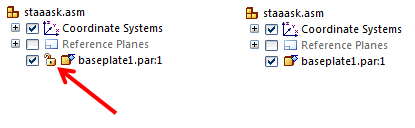
The lock icon shown in the illustration on the left indicates the document status. By default the document status is displayed.
All the illustrations in this tutorial do not display the current document status.
To turn off the document status, toggle the Display Status command (Data Management tab → Document Status group → Display Status ![]() )
)
To learn more about data management, search for Managing document properties in QY CAD help.
The PathFinder tab is used to review and edit the assembly structure. It is also used to hide and display assembly components, such as parts, subassemblies, coordinate systems, and reference planes.
Highlight the base plate part
-
In the top pane of PathFinder, position the cursor over the baseplate1.par entry, but do not click.
Notice that the base plate display changes color in the assembly window.
Move the cursor away and notice that the display returns to the previous color.
Select the base plate part
-
In PathFinder, position the cursor over the base plate part again, then click, and move your cursor away.
Notice that the part color in the graphics window changes to a different color than in the previous step.
Also notice that when selecting the part, the bottom pane of PathFinder displays the assembly relationships used to position the part, as shown below. Since this is the first part in the assembly, the relationship symbol that is displayed is the ground relationship.
![]()
When working in assemblies, temporarily highlight components using PathFinder, and also select them.
Display the coordinate systems collection
-
In the graphics window, click in free space to deselect the base plate part.
-
In PathFinder, position the cursor over the "+" symbol (1) adjacent to the Coordinate Systems collection, as shown above, and left-click.
Notice that an entry for the Base coordinate system (2) displays, as shown.
There is one Base coordinate system in an assembly document, located at the center of the design space. Any additional coordinate systems defined are added to the Coordinate Systems collection in PathFinder.
Hide the coordinate system
-
In PathFinder, position the cursor over the check mark (3) adjacent to the Base entry, then click to hide the coordinate system.
The coordinate system is hidden in the graphics window. Notice that the text in PathFinder for the Base entry has changed color.
Use the check boxes in PathFinder to display and hide assembly components.
The component entries in PathFinder also change color to indicate the current status of the assembly components.
If you have trouble placing parts
![]()
In the next activity, place and position the support part as shown. After placing the first part in an assembly, position the additional parts using assembly relationships.
-
On the Quick Access toolbar, click the Save button
 .
.Use the saved model in the next activity.
For the remaining tutorials, if a part is positioned incorrectly or the steps get confused, press Escape.
Then use the Select tool command on the Home tab to select the part, and press Delete to delete the part.
![]()
Back up to the step where part placement begins, and try again.
© 2021 UDS