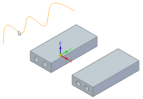
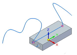
Route a 3D curve through circular faces
You can use the Route command to route a previously created 3D curve through circular openings in part or sheet metal, or in a 3D sketch in an assembly.
Use the 3D Draw group→3D Curve command  to create 3D sketch curves.
-
In a part or sheet metal document, select the 3D Sketching tab→3D Draw group→Route command
 .
.In an assembly document, the command is located on the Home tab.
-
Click a 3D curve.
-
Select the first circular face or feature for the curve route.
Clicking a circular feature routes the curve directly through both openings.
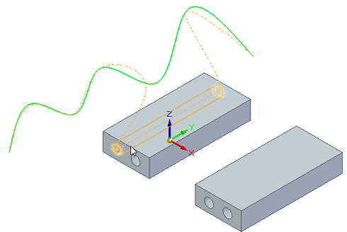
Clicking a face gives you options for a more flexible route.
-
Do one of the following:
-
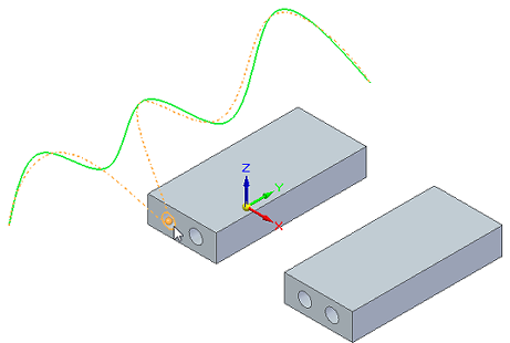
To continue routing the same 3D curve path, click another circular opening.
-
To see routing options, hover over another circular opening or feature, or press+hold the F key.
-
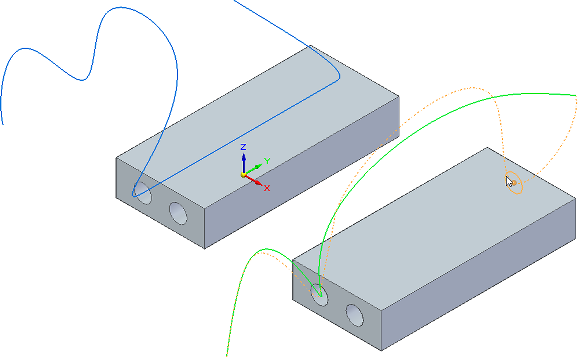
To route a different 3D curve, select the curve and click a circular opening.
-
-
When you are finished routing the 3D curve, right-click in the graphics window.
The Route command creates a connect relationship with the cylindrical openings. You can select and delete this relationship if needed.

© 2021 UDS