Tutorial: Create multiple studies
-
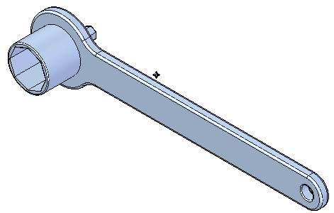
Open FE_bike_tool.par.
Simulation models are delivered in the \Program Files\UDS\QY CAD 2022\Training\Simulation folder.
-
Create a study simulating a force exerted on the handle.
-
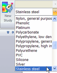
Assign a material to the part—On the Simulation tab→Study group, from the Material List, select Stainless Steel.
-
Select Simulation tab→Study group→New Study.

-
In the Create Study dialog box, set the following:
-
Study type=Linear Static
-
Mesh type=Tetrahedral
The study is created and is active, as indicated on the ribbon.
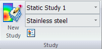
The new study also is listed in the Simulation study navigation pane.
-
-
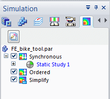
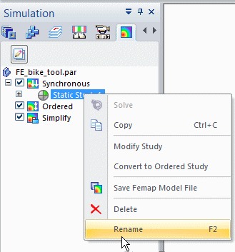
On the Simulation pane, click the minus box to the left of the study name to collapse the study.
-
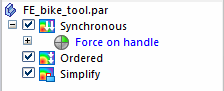
Right-click the default study name, and rename it to Force on handle.
-
-
Copy this study to create a second study. You will use this new study to model pressure exerted on the handle.
-
In the Simulation pane, right-click the Force on handle study and choose Create Copy from the shortcut menu.
Tip:You can quickly duplicate solved studies using the Create Copy command. This command copies everything in the study, including geometry, loads, constraints, connectors, meshes, and results.
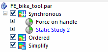
Another linear static study identical to the first is created. The name of the active study is displayed in blue.
-
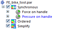
Collapse the new study, Static Study 2. Rename the study Pressure on handle.
-
-
Define a 445 newton (100 pound) force on the handle.
-
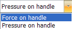
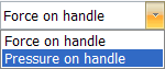
On the ribbon, in the Simulation tab→Study group, activate the Force on handle study by selecting it from the Study List.
-
Select Simulation tab→Structural Loads group→Force.

-
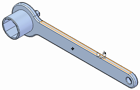
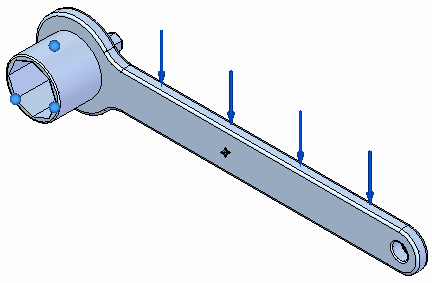
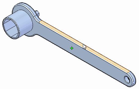
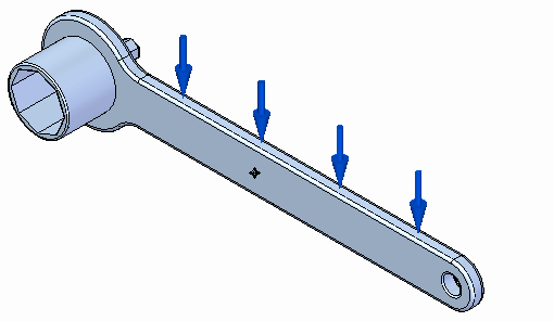
Select the top face of the handle.
-
Flip the direction
 , and then type a force value of 445 N.
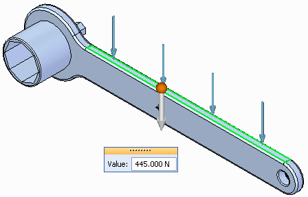
-
Select the Symbol Size/Spacing button
 .
. -
Change the Symbol Size to 8 using the slider. Select OK.
-
Right-click in space to accept, and then click to finish.
-
-
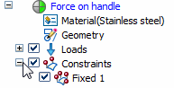
Define a fixed constraint in the Force on handle study.
-
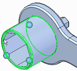
Use the Zoom Area command around the socket.
-
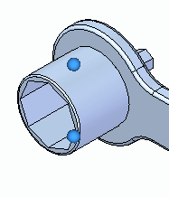
Select Simulation tab→Constraints group→Fixed, and select the cylindrical and end faces of the socket.
-
Right-click in space to accept, and then click to finish.
-
-
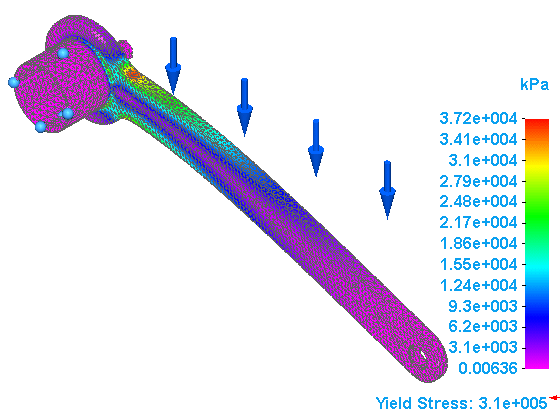
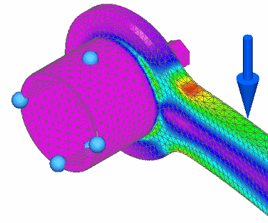
Solve the Force on handle study.
-
Select the Mesh command. In the Tetrahedral Mesh dialog box, use the slider to change the Subjective mesh size to 8.
-
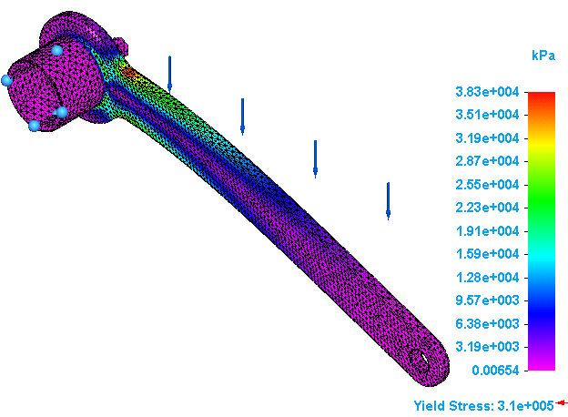
Click Mesh & Solve.
Note:The processing takes longer for the finer mesh size.
The results are displayed in the Simulation Results environment.
-
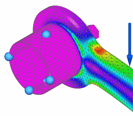
Use the Zoom Area command around the socket to observe the regions of highest stress.
-
On the ribbon, click Close Simulation Results.
-
-
Define a 276 kPa (40 lb/in2) pressure in the Pressure on handle study.
-
In the Simulation tab→Study group, activate the Pressure on handle study by selecting it from the Study List.
-
Select Simulation tab→Structural Loads group→Pressure.

-
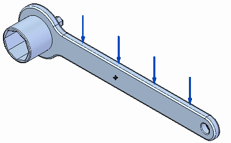
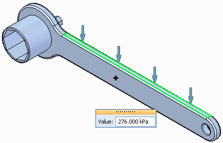
Select the top face of the handle.
-
Ensure that the direction points toward the handle. Type a pressure value of 276 kPa.
-
On the Loads command bar, select the Symbol Size/Spacing button
. -
In the Graphic Symbol Size dialog box, change the size to 8 using the slider. Select OK.
-
Right-click to finish, and then click to end the command.
-
-
Copy the fixed constraint from the Force on handle study.
-
Expand the Constraints collector in the Force on handle study.
-
Right-click the Fixed 1 constraint, and then press Ctrl+C.
-
In the Simulation pane, select the Pressure on handle study to make it the active study, and then press Ctrl+V.
When selected, the study name displays in blue text to indicate it is the active study.
The + symbol is added to the Constraints to indicate it is now populated.
In the graphics window, you can see fixed constraint symbols on the socket.
 Note:
Note:You can expand the Constraints collector in the Pressure on handle study to confirm that the Fixed 1 constraint was copied.
-
-
Mesh and solve the Pressure on handle study.
-
Repeat the previous steps for meshing the model and solving the analysis, but this time for the Pressure on handle study.
The results are displayed in the Simulation Results environment.
-
Use the Zoom Area command around the socket, so you can observe the regions of highest stress.
-
On the ribbon, click Close Simulation Results.
-
-
Navigate between studies using the Simulation pane.
The Show Single/All Studies button changes the display list in the Simulation pane to show all studies or just one study at a time. This is useful for managing multiple studies.
-
In the Simulation pane, click the minus button to collapse the Force on handle study. Do the same for the Pressure on handle study.
-
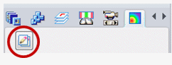
At the top of the Simulation pane, select the Show Single/All Studies button.
This displays the Show Next Study and Show Previous Study arrows, as shown below.
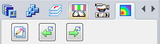
It also changes the display so that only one study at a time is shown in the Simulation pane.
-
Click the arrows to navigate between the studies in the Simulation pane.
-
Click the Show Single/All Studies button again to restore the original study list.
-
-
Close this file.
In this tutorial, you will create two simulation studies for a single model using copy and paste. Also, you will copy a constraint from one study to another.
| Tutorial: Copy and paste simulation items across part files |
© 2021 UDS