Activity: Add lip features
Add lip features
In this activity you will use the Lip command to define lip and groove features that fit the part together properly when it is assembled.
Launch the Activity: Add lip features.
Get ready to add features to the Mouse_bottom
-
In the PathFinder Design Bodies collection, clear the check marks in front of each of the design bodies except Mouse_bottom.
-
Right-click the Mouse_bottom body in PathFinder, and on the shortcut menu, select Activate Body.
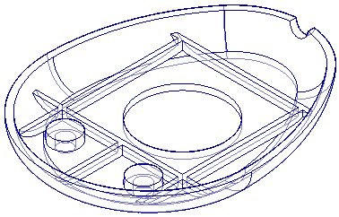
You will add a lip to the inner edge of the bottom piece of the mouse. To make this easier, hide the other bodies in the model.
Construct a lip
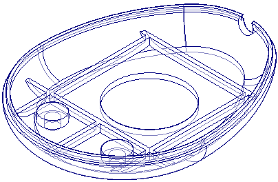
On the edges where the base and cover parts were divided from the original mouse part, you will construct lip and groove features so that the two new parts can be properly assembled.
-
Choose the Home tab→Solids group→Thin Wall list→Lip command
 .
.
Select an edge
-
Position the cursor approximately as shown, and then select the inside edge of the base.
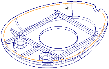
-
On the command bar, click the Accept button
 .
.
Specify the width, height, and orientation of the lip
-
On the command bar, type 1 mm as the width of the lip and 2 mm as the height.
-
Move the cursor around the edge you selected, and notice that a rectangle is displayed at different orientations, depending on the location of the cursor. The rectangle represents a profile that will be swept along the selected edge to form a lip or groove.
-
Position the cursor above the part edge, so that the lip profile lies above the part, and click.
Note:The location of the rectangle in your model may be different than shown.
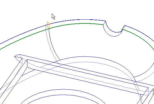
Finish the lip
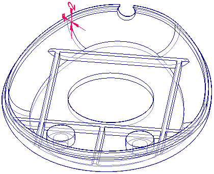
-
On the command bar, click the Finish button.
Save the file
-
Click Cancel to close the command bar.
-
Click the Save button
 to save the work you have done so far.

Activate Mouse_top
-
In the PathFinder Design Bodies collection, check Mouse_top and un-check each of the other design bodies.
-
Right-click the Mouse_top body in PathFinder, and on the shortcut menu, select Activate Body.
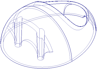
You will add a groove to the inner edge of the top piece of the mouse. To make this easier, hide the other bodies in the model.
Construct a groove
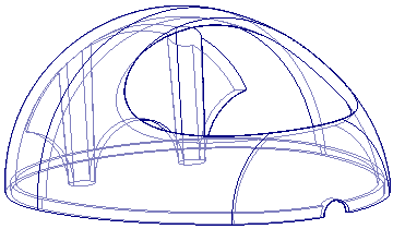
On the edge where the cover part was divided from the original mouse part, you will use the Lip command to construct a groove, so that the part can be properly assembled with the base.
-
Choose the Home tab→Solids group→Thin Wall list→ Lip command
 .
.
Select an edge
-
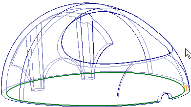
Select the inside edge at the bottom of the cover, as shown.
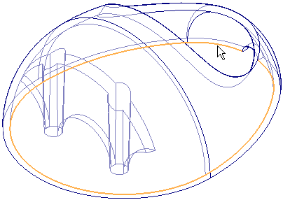
-
On the command bar, click the Accept button
 .
.
Specify the width, height, and orientation of the groove
-
On the command bar, type 1 mm as the width of the lip and 2 mm as the height.
-
Position the cursor above the part edge, so that the groove profile lies within the shell of the part, and click.
Note:The location of the rectangle in your model may be different than shown.
Finish the groove
-
On the command bar, click the Finish button.
Save the file

-
Select Cancel to close the Lip command and then save
 the changes you made to the file.
Publish the design bodies as parts
-
Choose the Home tab→Solids group→Add Body list
 →Multi-body Publish command
  .
. -
On the Multi-body Publish dialog box, note that you can specify names and locations of part files to represent each design body in the model.
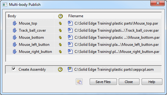
You can also choose to publish an assembly of the parts.
-
On the Multi-body Publish dialog box, click Save Files to create the new files.
The new parts that are published from the original multi-body model each consist of a part-copy feature, so that the new models are associative to the original multi-body model. Similarly, if you choose to publish an assembly, the assembly model is associative to the original multi-body part model.
-
On the Multi-body Publish dialog box, click Close.
Now that you have created separate design bodies to represent the components of the original solid model, you can publish each body to a part file and publish an assembly of the parts.
Save the part
-
Click the Save button
 to save the part.
 -
Close the file.
© 2021 UDS