Activity: Divide a part into smaller parts
Split the model into separate bodies
In this activity you will use the Split command to divide the molded part into several bodies.
Launch the Activity: Divide a part into smaller parts.
Show Surface 1 and Surface 2
In the next few steps, you will divide the part into several pieces. You will use two construction surfaces and two reference planes to accomplish this.
-
In PathFinder, select the check boxes next to the surface entries labeled Extrude 1 and Extrude 2. The icons look like this:

Alternatively, you can use the View tab→Show group→Construction Display command  to display the surface entries. For more information, see Construction Display command.
Display the reference planes
-
In PathFinder, expand the Base Reference Planes group.
-
Select the check boxes next to the Top (xy) plane and Right (yz) planes.
Split the part
-
Click Save
 to save the file.
 -
Choose the Home tab→Solids group→Add Body list
 →Split command
  .
. -
If a dialog box displays asking you to save the part again, click OK.
You will split the single design body and single part document into several pieces, each in its own part document. Yet, the original part and part document will remain, and the published parts will be associatively dependent on the original part.
Select the target body
The Split command splits a target body into multiple bodies, using a tool body to define the split boundary.
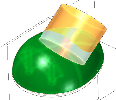
You will use a surface to split a circular plate from the bottom of the mouse body. The first prompt for the Split command is to select the body that you will split.
-
Select the mouse body, as shown.

Select the dividing surface
-
Select the surface shown.
-
On the Split command bar, click the Accept button
 .
. -
Click the Finish button to complete the split.
Prepare to split the part again

In PathFinder, notice that the Design Bodies collector now contains two design bodies. The second body is the portion of the original body that was split out by the cylindrical surface. Your design body numbers may be different than shown here.
In the next steps, you will continue to split the model into additional bodies.
Select the target body
The Split command should still be running. If not, select the command again.
You will split another portion of the original design body.
-
Select the mouse body, as shown.
Select the dividing surface
-
Select the top reference plane, as shown.

-
On the Split command bar, click the Accept button
, and then click Finish.
Prepare to split the part a third time
-
Ensure that the Split command is running.
-
Select the mouse cover as the body to split.

In PathFinder, notice that there are now three design bodies. The plane split the mouse base from the mouse cover.
Select the dividing surface
-
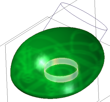
Select the cylindrical extruded surface that passes through the center of the part, as shown.
At the current view orientation, you are viewing the cylindrical surface on edge. When you finish defining this cut, the surface shape will be easier to see.
-
On the Split command bar, click Accept, and then click Finish.
Prepare to split the part a fourth time
-
Ensure that the Split command is still running.
Next, you will split the body that was produced in the previous step.
-
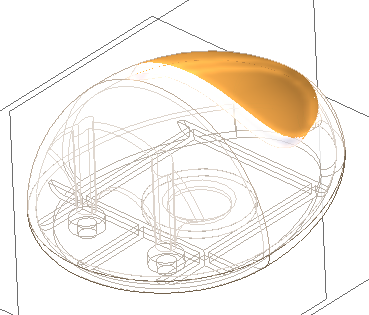
Select the body within the cylinder as the target of the split, as shown.
Notice that a fourth design body has been added to the Design Bodies collection in PathFinder.
Select the dividing surface
-
Select the right reference plane, as shown.

-
On the Split command bar, click the Accept button, and then click Finish.
-
You have finished splitting the model into separate design bodies, so press the Escape key to end the Split command
Rename the design bodies
-
In PathFinder, right-click the first design body and notice which body is highlighted in the model. Then in the shortcut menu click Rename, and in PathFinder type the appropriate name.
Use the following names to give all the design bodies the appropriate name; Track_ball_cover, Mouse_bottom, Mouse_top, Mouse_left_button, Mouse_right_button.
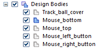
You have now finished splitting the original design body into five separate design bodies. Later in this tutorial, you will publish the separate bodies as individual parts and an assembly, so it will be helpful to give meaningful names to the multiple design bodies within the model now.
Close the Divide Part dialog box
-
This completes splitting the original single mouse body into five named bodies. In this part of the activity you used surfaces and planes to create the separate design bodies.
Notice that the entire part is now displayed. In the next few steps, you will add features to two of the new parts you created.
© 2021 UDS