Activity: Add draft to the part
Add draft to the part
In this activity you will add draft to the interior features of the molded part body.
Launch the Activity: Add draft to the part.
Add draft to the interior of the part
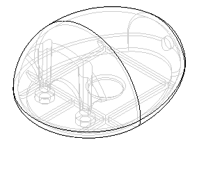
You will add draft to the web network, rib, and other features on the interior of the model. Draft will be added in opposite directions above and below the planar face which is the top face of the web network.
-
Choose the Home tab→Solids group→Draft command
 .
.
Specify the draft options
-
On the command bar, click the Draft Options button
 .
. -
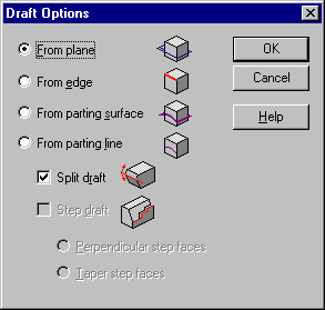
In the Draft Options dialog box, select the From Plane and Split Draft options. Click OK.
With these options, you will specify two draft angles, and these will be applied in opposite directions above and below a planar face.
Specify the draft plane of reference
-
On the command bar, in the Create-From Options list, set the Coincident Plane option.

-
Position the cursor over the top, planar face of the web network you created earlier, stop moving the mouse for a moment, and notice that the cursor image changes to indicate that multiple selections are available.

-
Right-click to display the QuickPick tool. Move the cursor over the different entries in QuickPick, and notice that different faces of the model highlight.
QuickPick allows you to select exactly the element you want, the first time, without having to reject unwanted elements.
-
Use QuickPick to highlight the face labelled Plane (Web Network) as shown, and then click to select it.
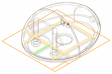
A new reference plane is created coincident to the selected face.
Select faces to add draft to
-
On the command bar, set the Select option to All Normal Faces.
With this option, with a single selection, you can select each face in the model that is perpendicular to the draft plane of reference.
-
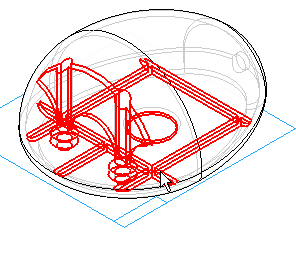
Position the cursor over the center of the part, and select the faces shown.
Deselect a face
-
On the command bar, set the Select option to Face.

-
While holding the Shift key, position the cursor over the cylinder at the center of the part, and use QuickPick to deselect the Cylinder (Cutout2), as shown.
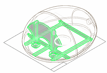
Notice that the other faces you selected in the previous step remain selected.
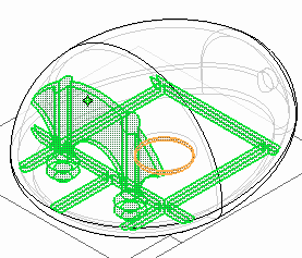
It is convenient to select many faces with so little input. However, you may not wish to apply draft to every face in the select set. You can set the Select filter to one of the other options and continue to add faces to the select set, or by holding the Shift key, you can individually deselect faces.
Specify the draft angles
-
On the command bar, set both Draft Angle 1 and Draft Angle 2 to 1.5 degrees.

-
On the command bar, click the Accept button
 .
.
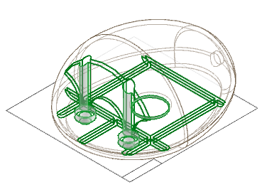
Specify the draft direction
-
On the command bar, click the Next button.
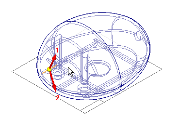
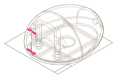
Notice that lines are shown to illustrate the direction in which draft will be applied to the selected faces. The lines labeled 1 and 2 represent the two draft angles you specified in the previous step, and the third line represents an edge of the selected geometry that is the reference for the draft angles.
-
Position the cursor so that the draft angles are applied as shown, and click.
 Note:
Note:If you see a warning dialog box indicating that the feature could not be constructed, do not be alarmed. Continue to the next step for instructions on how you can correct this.
Finish the feature
-
If the add draft feature was constructed successfully, on the command bar, click Finish. If the feature was unsuccessful, follow the instructions below.
If the operation was unsuccessful
In the Draft Direction step you just completed, it is sometimes difficult to see the relationship between the display of the draft angles and the faces to which draft is being applied. If the operation was unsuccessful because of invalid topology, it is because the draft direction you chose resulted in draft being applied inward, from the reference plane to the top and bottom of the part. Applying draft in this direction consumes entire portions of the solid, leaving an invalid topology, so the feature fails. To correct this, on the Operation Unsuccessful dialog box, click OK, and then on the command bar click the Draft Direction step, and choose the opposite direction than you chose in the previous step. The feature should then compute correctly.
Save the file

-
Click the Save button
 to save the work you have done so far.
© 2021 UDS