Activity: Define the body of a molded plastic part
Define the body of a molded plastic part
In this activity you will use the Web Network command to create the body cavity of a molded plastic part. Then you will use the Rib command to add internal ribs to strengthen the structure.
Launch the Activity: Define the body of a molded plastic part.
Open the activity file
-
Open ...\Program Files\UDS\QY CAD 2022\Training\seppcpl.par.
Save a new version of the file
-
Select the QY CAD Application button,
 and then click Save As.
 -
In the Save As dialog box, save the part to a new name or location so that other users can complete this tutorial using the original part file.
Later in the tutorial, you will save several other related files, and you might find it easier to work with these files if you save them all to the same location with similar names, such as mouse_1.par, mouse_2.par, and so on.
Get to know the part
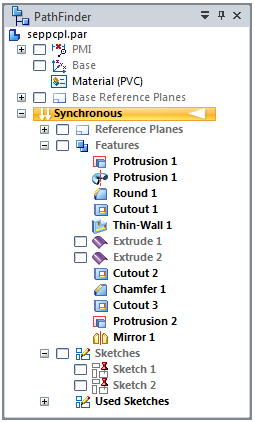
You will be using PathFinder in this tutorial.
In addition to the features already created, the model contains two sketches and two construction surfaces that you will use to construct other features later. You will ensure that they are displayed in the next step.
Notice that the interior of the part was hollowed by constructing a Thin Wall feature with no open faces. Ordinarily, of course, this could not be manufactured. However, later in the tutorial you will use multi-body modeling commands to divide the single, hollow model into several thin pieces.
Transition from a synchronous to an ordered part
![]()
The overall shape and major features of this part were constructed in the synchronous environment. In this tutorial, you will create additional features using ordered methods.
-
Right-click the Synchronous header in PathFinder and select Transition to Ordered.
Notice that an Ordered header appears in PathFinder, and it is illuminated, meaning you are now operating in the Ordered environment.

Any subsequent features you construct are based on ordered methods.
Display the sketches
-
Choose the View tab→Show group→Construction Display command
 .
. -
In the Show All/Hide All dialog box, on the Sketches row, select the Show All check box and click OK.
All sketches are displayed on the part, as shown.

-
Expand the Sketches collector in PathFinder and move your cursor over the Sketch 1 and Sketch 2 entries. As you do this, observe the highlighted sketch elements on the part.
-
Clear the check mark in front of the Sketch 2 entry, leaving only Sketch 1 displayed, as shown.

Construct a Web Network
You will construct a network of strengthening ribs on the base of the part.
-
Choose the Home tab→Solids group→Thin Wall list→Web Network command
 .
.
Select profile elements from the sketch
-
On the command bar, in the Create-From Options list, set the Select From Sketch option.
-
Select each of the green lines in the sketch in the order shown.
-
On the command bar, click the Accept button.

Specify the thickness
-
On the command bar, type 1.5 as the thickness of the web, and then press Enter.
Specify the extent direction
-
Move the cursor above and below the profile, and notice that the web network can be extended up or down.
-
Position the cursor below the profile so that the feature is extended downward, and then click.
Finish the feature and turn off Sketch 1
-
On the command bar, click Finish.
-
In the Ordered portion of PathFinder, move your cursor onto the Web Network entry and observe the highlighted web network feature on the model.
-
In PathFinder, clear the check box next to Sketch 1 to hide the sketch.
Turn on Sketch 2 and save the file
-
In PathFinder, select the check box next to Sketch 2 to display the sketch.
-
Click the Save button
 located at top-left in the application window to save the work you have done so far.
Construct a rib
You will construct a strengthening rib at the top of the cavity of the mouse.
-
Choose the Home tab→Solids group→Thin Wall list→Rib command
 .
.
Select a profile element from the sketch
-
On the command bar, in the Create-From Options list, set the Select From Sketch option.
-
Select the profile in the sketch, as shown.
-
On the command bar, click the Accept button
.
Specify the thickness
-
On the command bar, type 1.5 as the thickness of the rib, and then press Enter.
Specify the direction of the rib
-
Move the cursor around the rib profile, and notice that an arrow extends from the rib in one of four directions, depending on where you position the cursor:
-
Position the cursor so that the arrow points above the profile, as shown, and click.
 Note:
Note:The position of the arrow may be different than shown in the illustration.
Finish the feature and turn off Sketch 2
-
On the command bar, click Finish.
-
Clear the check box next to Sketch 2.
-
In the Ordered portion of PathFinder, move your cursor onto the Rib 1 entry and observe the highlighted rib feature on the model.
Save the file
-
Click the Save button
to save the work you have done so far.
© 2021 UDS