Activity: Creating a boss feature
Creating a boss feature
In this activity you will create a mounting boss from a parallel plane and open sketch, add dimensions to the boss feature using SmartDimension and Distance Between dimensions.
Launch the Activity: Creating a boss feature.
Construct a protrusion
![]()
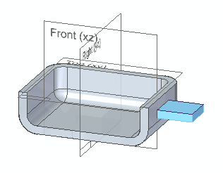
You will construct a mounting tab on the part, as shown in the illustration. You will use the Extrude command for this.
-
On the Home tab→Solids group, choose the Extrude command
 .
.
Create a parallel reference plane
The first step in constructing this feature is selecting a profile plane to draw the shape of the feature on. However, there are no reference planes at the location where you will construct the feature. So you need to create a reference plane parallel to an existing face or reference plane.
-
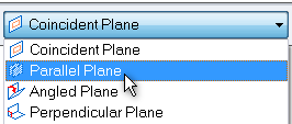
On the command ribbon bar, in the Create-From Options list, click the Parallel Plane option.
-
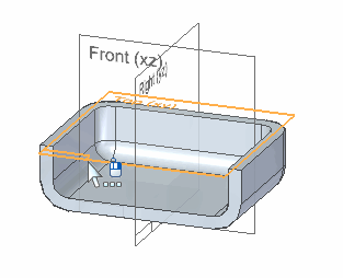
Select the top reference plane, as shown.
You can use QuickPick to help you select the reference plane.
Position the reference plane
-
On the Extrude command bar, type 10 in the Distance box, then press the Enter key.
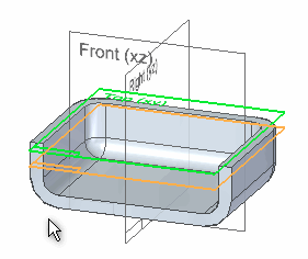
Notice that, by moving the cursor around the top face of the part, you can position the parallel reference plane inside or outside the part.
-
Move the cursor to position the reference plane inside the part, as shown, and then click.
The view changes to a true profile view.
Evaluate the profile
![]()
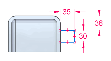
Next, draw and dimension the profile for the mounting tab as shown in the illustration. You will:
-
Use the Line command to draw the three lines shown in blue.
-
Use the SmartDimension command to define the 30 mm and 35 mm dimensions.
-
Use the Distance Between command to define the 36 mm dimension.
Pan the view
![]()
-
At the bottom-right side of the QY CAD application window, choose the Pan command
 .
. -
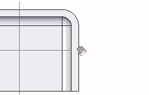
Position the cursor as shown in the illustration, hold the left mouse button down, then drag the cursor to reposition the geometry to the center of the view, as shown below.
-
Right-click to exit the Pan command.
Start the first line
-
On the Home tab→Draw group, choose the Line command
 .
. -
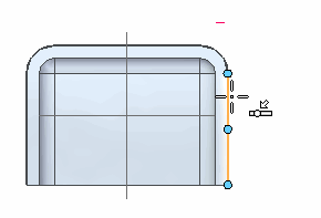
Position the cursor as shown, and when the point on element relationship indicator
 appears adjacent to the cursor, click to start the line.
-
Move the cursor to the right.
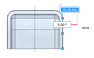
Notice the following:
-
A line stretches to follow the cursor wherever you move it.
-
When the line is horizontal, a horizontal relationship indicator
 appears next to the cursor.
-
Finish the first line
![]()
-
Move the cursor until:
-
The horizontal relationship indicator
 appears at the cursor.
 -
The length displayed on the command bar is approximately 35 mm.
-
The angle on the command bar is zero degrees.
-
-
When the line is horizontal, and approximately 35 mm long, click to finish the first line.
Draw the second line
![]()
By typing the length and angle on the command bar, you can draw lines the exact length and angle you want.
-
If it is not already highlighted in blue, click the Length box on the command bar.
The Line command is still active, so the next line will start at the endpoint of the line you just drew.
-
Type 30, and press the Enter key.
Notice that the Length box updates and the Angle box becomes active.
-
Move the cursor around the screen and notice that the line length is locked at 30 mm.
-
Move the cursor down until the vertical relationship indicator
 appears. Notice that the line angle locks at -90 degrees.
 -
Click to place the second line.
When you know the length or angle you want, you can type exact values in the command bar.
Draw the third line
![]()
-
Position the cursor as shown, and when the point on element and horizontal relationship indicators
 appear adjacent to the cursor, click to finish the line.
 -
When you finish drawing the line, right-click to restart the Line command.
Observe the results
![]()
Take a few moments to observe the finished profile.
In addition to the horizontal, vertical, and endpoint connect relationships you learned about earlier, two point on element relationships (1) and (2) were used for this profile.
The point on element relationships connect the horizontal lines you drew to the vertical edge on the part, but the horizontal lines are still free to move up and down.
In the next few steps, use dimensions to finish defining the size and position of the profile elements.
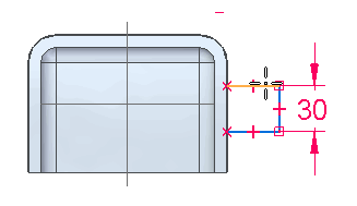
Dimension the vertical line
-
On the Home tab→Dimension group, choose the SmartDimension command
 .
. -
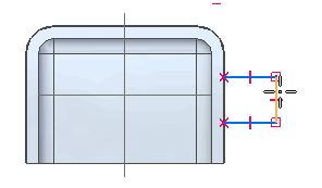
Position the cursor over the vertical line you just drew, as shown. When the line highlights, click to select it.
-
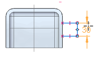
Move the cursor to the right, and then click to define the dimension location.
-
If the dimension value is not exactly 30 mm, type 30 on the command bar, then press the Enter key.
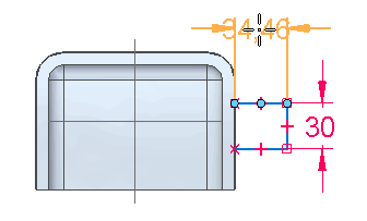
Dimension the horizontal line
-
The SmartDimension command
 should still be active.
 -
Position the cursor over the horizontal line. When the line highlights, click to select it.
-
Move the cursor above the profile, then click to define the dimension location.
The dimension value of this line may not be exactly 35 mm, because you approximated the length of the line when drawing it.
-
If the dimension value is not exactly 35 mm, type 35 on the command bar, then press the Enter key.
Select the Distance Between command
![]()
You have finished defining the size of the profile. Place a dimension to define the location of the profile on the part.
-
On the Home tab→Dimension group, choose the Distance Between command
 .
. -
On the Dimension command bar, on the Properties page, ensure that the Horizontal/Vertical option is set.

Select the elements to dimension
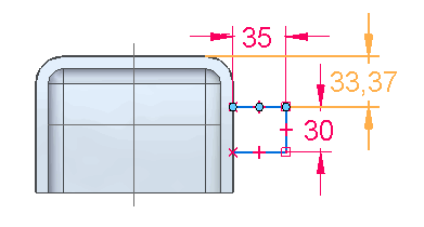
-
Position the cursor over the edge of the part as shown. When the edge highlights, click.
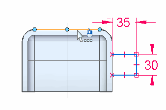
If QuickPick appears, either QuickPick selection is valid. There are two edges available in this situation.
-
Position the cursor over the horizontal line shown. When the line highlights, click.
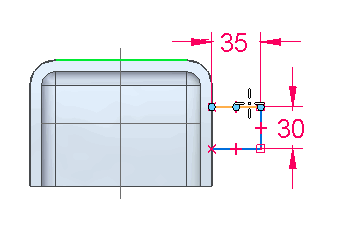
Define the dimension orientation
-
Move the cursor around the screen and notice that the dimension orientation changes to indicate that multiple solutions are available.
-
Position the cursor, as shown, and click to position the dimension.
-
On the command bar, type 36, then press the Enter key.
Close the profile view
![]()
-
Choose the Close Sketch command
 to return to the 3D model view.
Specify the material direction
-
Choose the Fit command
 to fit the contents of the view to the graphics window.
 -
On the Extrude command bar, notice that the Side Step is active.
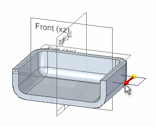
Also notice that in the graphics window, a red arrow appears on the profile you just drew.
Because this profile is open, you must define the side on which you want to add material.
As you move the cursor, the arrow points either outward away from the profile, or inward toward the center of the profile.
This arrow determines the side of the profile which material is added to the part
-
Position the cursor so that the arrow points inward, and then click to define the material direction.
Project the profile
-
On the Extrude command bar, type 8 in the Distance box for the extent of the feature, then press the Enter key.
-
Position the cursor below the profile, and then click to finish defining the extent.
-
On the Extrude command bar, click the Finish button
 .
.
Fit and save the part
![]()
-
Choose the Fit command
 to fit the contents of the view to the graphics window.
 -
Choose the Save command
 to save the work you have done so far.
© 2021 UDS