Activity: Create a family of assemblies
Create a family of assemblies
In this activity you will learn how to create new members for a family of assemblies .
Launch the Activity: Create a family of assemblies.
Open the activity file
-
Open ...\Program Files\UDS\QY CAD 2022\Training\seaacfa.asm
Save a new version of the assembly
-
At the top-left side of the application window, click the Application button
 .
. -
On the Application menu, choose Save As.
-
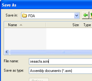
On the Save As dialog box, save the assembly to a new name or location so that other users can complete this tutorial using the original assembly file.
Later in the tutorial, you will save another new file, so you might find it easier to work with these files if you save them all to the same location.
Arrange your work space
![]()
-
To make it easier for you to work through this tutorial, close any other QY CAD files you have open.
Display individual colors for the assembly
-
Choose the View tab→Style group→Color Manager command
 .
. -
On the Color Manager dialog box, ensure the following options match the illustration:
-
Set the Use Individual Part Styles option.
-
Set the Show And Allow Assembly Style Overrides option.
-
Clear the Show Part Face Colors option.
-
-
On the Color Manager dialog box, click OK.
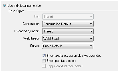
When working in an assembly, you can display all the parts in one color, or you can display the individual colors assigned to the parts. Depending on the current settings for your computer, the parts may be displayed all in one color, or in multiple colors.
Activate the parts in the assembly
-
In PathFinder, position the cursor over the entry for seaacfa.asm, as shown, then right-click to display the shortcut menu.
-
On the shortcut menu, choose Activate.
The display updates to indicate that all the parts are active.
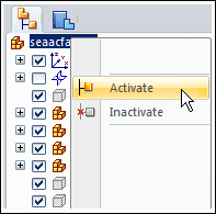
To ensure that your display matches the tutorial illustrations, you will activate all the parts in the assembly.
Open the Family of Assemblies tab

-
From the list of docking panes, open the Family of Assemblies tab
 .
.In the next few steps, you will use the options on the Family of Assemblies tab to create a new family of assemblies.
You create a family of assemblies by converting a normal assembly document into an alternate assemblies document. You can only convert the assembly document once, and you must specify whether you want to convert it into a family of assemblies or an alternate position assembly. In this tutorial, you will convert the assembly into a family of assemblies.
To learn more, see Alternate Assemblies.
Create a new family of assemblies
-
On the Family of Assemblies tab, click the New button
 .
. -
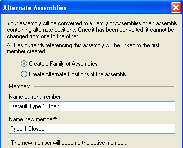
On the Alternate Assemblies dialog box, do the following, as shown in the illustration:
-
Ensure that the Create A Family Of Assemblies option is set.
-
In the Name Current Member box, type: Default Type 1 Open, then press the Tab key.
-
In the Name New Member box, type: Type 1 Closed.
-
On the Alternate Assemblies dialog box, click OK.
-
Observe the active member

On the Family of Assemblies tab, notice that the Type 1 Closed member is the active member. When you create a new family of assemblies, the name you type in the Name New Member box becomes the active member.
Ensure that Apply edits to all members is unchecked.
Display the Member Variables option
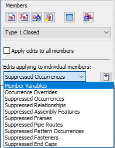
In the next few steps, you will modify the Type 1 Closed family member by overriding the value of the angular relationship that controls the position of the Valve subassembly and handle. First you will add the variable to the Member Variables list.
-
On the Family of Assemblies tab, set the Member Variables option.
Display the Variable Table
-
Choose the Tools tab→Variables group→Variables command
 .
.The Variable Table dialog box is displayed. It is possible that the variable table on your computer is blank by default.
If so, the variable table has a filter that allows you to control which dimensions and variables are displayed.
-
If your variable table is blank, on the Variable Table dialog box, click the Filter button
 .
. -
On the Filter dialog box, set the Named By option to Both, and set the Graphics In option to File, then click OK.
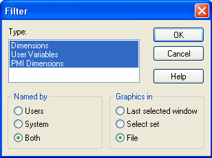
Your variable table should now display similar to the illustration at the top of the page.
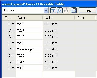
Add a variable to the Member Variables list
-
Position the cursor adjacent to the ValveAngle variable row, as shown in the illustration, then click to select it.
Note:The Modify dimension command bar is displayed as a way to change the value of the Valve Angle. Ignore this.
-
On the Family of Assemblies tab, click the Add Variables button
 . The variable is added to the Member Variables list.
When you add variables to the Member Variables list, you can no longer edit them within the Variable Table. You must edit them in the Member Variables list on the Family of Assemblies tab.
-
Dismiss the Variable Table by clicking the X on the Variable Table dialog box.

Prepare to edit the ValveAngle variable
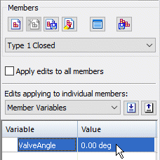
-
In the Member Variables list, position the cursor over the variable as shown in the illustration above, but do not click yet.
In the graphics window, notice the faces used to define the angle relationship highlight, as shown below.
![]()
Edit the ValveAngle variable
-
Position the cursor over the ValveAngle variable Value box, then double-click the left mouse button.
-
Clear the existing text, then type 90, and then press Enter.

Observe the effects of the change
![]()
In the graphics window, notice that the handle rotated 90 degrees clockwise.
Although you cannot see the internal parts in the shaded window, the valve subassembly also rotated.
Activate the Default family member

-
On the Family of Assemblies tab, select the Default Type 1 Open member, as shown in the illustration.
Observe the Default family member
![]()
Notice that for the Default Type 1 Open member, the ValveAngle variable was also added to the Member Variables list, but the valve handle is still in the open position. The variable value you changed only affected the Type 1 Closed family member.
When you add a variable to the Member Variables list for one member, the variable is added to the Member Variables list for all members that contain the variable, but each member can have a different value assigned to the variable.
© 2021 UDS