Activity: Construct a groove weld
Construct a groove weld
In this activity you will learn how to create a chamfer and place a groove weld.
Launch the Activity: Construct a groove weld.
Reorient the view
-
On the keyboard, hold the Ctrl key down, then press the I key to rotate the view back to the isometric orientation.
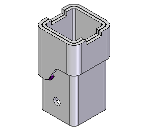
In the next few steps, you will add a chamfer feature to the TopLeg part to prepare the component for a groove weld feature.
Hide the Mount1 component
-
On the Home tab, the Select command should be active. If not, choose Select
 .
. -
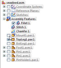
In PathFinder, position the cursor over the check mark adjacent to the Mount1.par component, then click to hide the component.
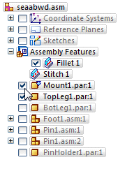
The Mount1.par component is hidden in the graphics window. This will make it easier to select the proper edges for the chamfer feature.
Chamfer part edges
-
Choose the Features→Assembly Features→Round list→Chamfer command
 .
. -
On the Assembly Features Options dialog box, set the Create Assembly Features option, and click OK.
Assembly features create all feature geometry in the assembly document (profile and solid geometry).
Assembly Driven part features create the profile geometry in the assembly, but place the solid geometry in the affected part documents using inter-part associativity functionality.
For more information, see the Assembly-based Features Help topic.
-
On the Chamfer command bar, click the Chamfer Options button
 and ensure the Chamfer Options dialog box is set to Equal Setbacks.
 -
On the Chamfer command bar, ensure the Select option is set to Chain.
You will prepare the top leg part for a groove weld feature by chamfering the top edges.
![]()
Select the edges to chamfer
-
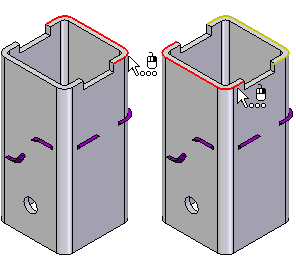
Use QuickPick to select the two sets of edges on the Topleg1.par component as shown.
-
First select the edge set shown in the left illustration, then select the edge set shown in the right illustration.
-
On the command bar, in the Setback box, type 7, then press Enter.
Finish the chamfer
-
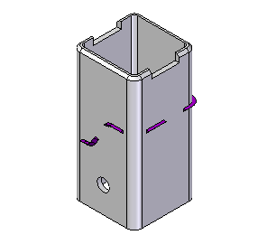
On the command bar, click Finish.
Display the Mount1 component
-
Choose the Home→Select→Select command
 .
. -
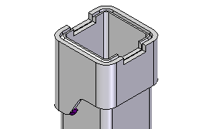
In PathFinder, click the check box adjacent to the Mount1.par component to display the component.
The Mount1.par component is redisplayed in the graphics window.
Zoom in closer
-
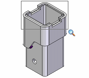
On the Viewing commands toolbar, click Zoom Area
 .
. -
Click above and to the left, as shown, and then again below and to the right.
-
Right-click to end the Zoom Area command.
Construct a groove weld
-
Choose the Features→Assembly Weld Features→Groove Weld command
 .
. -
If the Groove Weld Options dialog box displays, click OK to dismiss it.
![]()
In the next few steps, you will construct a groove weld between the mount and top leg parts.
Select the base faces
-
On the Groove Weld command bar, ensure that the Select option is set to Chain.
-
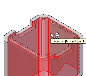
Use QuickPick to highlight the chain of faces on the Mount1.par part shown, and then click the left mouse button to select them.
-
On the command bar, click Accept
 .
.
Select the target faces
-
On the command bar, ensure that the Select option is set to Chain.
-
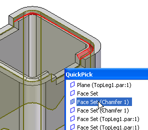
Use QuickPick to highlight the chain of faces on the TopLeg1.par part shown, and then click the left mouse button to select them.
-
On the command bar, click Accept
 .
.
Select the target top-path
-
On the command bar, ensure that the Select option is set to Chain.
-
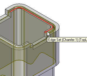
Select the top edge of the faces you selected in the previous step, as shown.
-
On the command bar, click Accept
 .
.
Select the target bottom-path
-
On the command bar, ensure that the Select option is set to Chain.
-
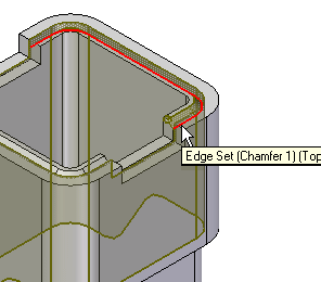
Select the bottom edge of the faces you selected in the previous step, as shown.
-
On the command bar, click Accept
 .
.
Finish the groove weld
-
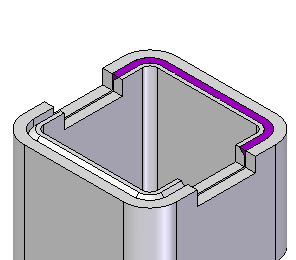
On the command bar, click Preview.
-
On the command bar, click Finish.
For more information on constructing groove welds, see the Groove Weld command Help topic.
You have now defined the necessary parameters for the groove weld.
Groove weld features use lofting technology to construct a weld bead using the faces and edges you selected as input.
Save the file
![]()
-
On the Quick Access toolbar, click Save
 .
.
© 2021 UDS