Create a new Assembly
Creating a new assembly
In this activity you will learn to create a second assembly file.
Launch the Create a new Assembly.
Create a new assembly
![]()
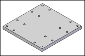
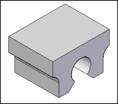
In the next few steps, create the assembly shown in the top illustration: a plate with four blocks.
-
On the Application menu, click New→ISO Metric Assembly.
This tutorial uses metric units of measure. If English units were selected during QY CAD installation, select a metric template. On the Application menu→New→New dialog box, click the ISO Metric template and then select iso metric assembly.asm. Click OK.
Place the plate part
-
Choose the Home tab→Components group→Insert Component command
 .
. -
On the Parts Library tab, select the file named plate.par, hold down the left mouse button, drag the file into the assembly window, then release the mouse button.

![]()
Use PathFinder to turn off the coordinate system display
![]()
-
In PathFinder, clear the check box on the Coordinate Systems entry.
Save the assembly
![]()
-
Click Save
 , and on the Save As dialog box, save the assembly in the Training folder as plate.asm.
Place the block part
-
Click the Parts Library tab.
-
In the Parts Library pane, select the file named block.par, hold down the left mouse button, drag the file into the Assembly window, then release the mouse button.

![]()
Mate the block part to the plate part
![]()
Notice that the FlashFit option ![]() is already active by default.
is already active by default.
Use FlashFit to define a mate relationship between the top face of the block and the top face of the plate.
-
Use QuickPick to select the top face of the block, as shown above.
Select the mating face on the plate part
-
If the face shown in the illustration highlights, left-click select it.
-
If another face highlights, right-click to display the QuickPick list, position the cursor over the entry in QuickPick that highlights the face shown, then left-click to select it.
![]()
When QuickPick highlights the element to select, bypass QuickPick list and to select the highlighted element.
Observe the result and flip the block
![]()
The block part is positioned in the assembly approximately as shown. Notice that the face on the block part is coplanar to the face on the plate.
When positioning parts, FlashFit positioning logic analyzes the relative position of the faces selected to determine whether to apply a planar align or a mate relationship.
FlashFit applies the relationship that requires less part rotation. In this case, a planar align relationship was the nearest solution.
For this part, a mate relationship is required.
-
On the Assemble command bar, click the Flip button
 to change the planar align relationship to a mate relationship.
The part is repositioned approximately as shown in the bottom illustration.
![]()
Align the block part to the plate part
![]()
Next use FlashFit to apply a planar align relationship between a planar face on the block and a planar face on the plate.
Select the face to align on the block part
![]()
-
Select the face shown.
Select the aligning face of the plate part
![]()
-
Select the face shown.
Observe the result
![]()
The faces selected are aligned.
In the next steps, apply another planar align relationship to align the front faces of the block and plate.
Select the face to align on the block part
![]()
-
Select the face shown.
Select the aligning face on the plate part
![]()
-
Select the face shown.
Observe the result
![]()
The block part is fully positioned in the assembly.
Place another block part
-
Click the Parts Library tab.
-
Drag another block from the Parts Library tab and drop it into the assembly at the approximate location shown.
![]()
Use FlashFit to apply the same relationship types as for the first block.
First define a mate relationship between the top face of the block and the top face of the plate.
Select the mating face on the block part
![]()
-
Select the face shown.
Select the mating face on the plate part
![]()
-
Select the face shown.
Flip the block
![]()
The block part is positioned in the assembly similar to the top illustration.
-
On the Assemble command bar, click the Flip button
 to change the planar align relationship to a mate relationship.
The part is repositioned approximately as shown in the bottom illustration.
![]()
Select the face to align on the block part
![]()
Now align a face on the block with a face on the plate.
-
Use QuickPick to select the face shown.
Select the aligning face on the plate part
![]()
-
Use QuickPick to select the face shown.
Observe the result
![]()
The faces selected are aligned.
In the next steps, apply another planar align relationship to align the front faces of the block and plate.
Select the face to align on the block part
![]()
-
Use QuickPick to select the face shown.
Select the aligning face on the plate part
![]()
-
Use QuickPick to select the face shown.
Observe the result
![]()
The second block is now fully positioned in the assembly.
Place the last two blocks
![]()
-
Use the Parts Library tab to drag and drop the block part into the assembly two more times and position the blocks in the other two corners of the plate.
-
Use the same steps used to place the first and second blocks. The mating faces will be the same, but the faces to align will be different than in the previous steps.
-
Remember to use the Flip button when applying the first relationship.
-
If a relationship is placed incorrectly, use the Select tool to select the incorrectly placed part; then use the Delete command on the Edit menu (or just press Delete) to delete the part.
-
Then repeat the process of placing the part.
-
You can also use the Previous and Next buttons in the tutorial window to review the steps you used to position the previous block parts.
-
Save and close the second assembly
-
When this subassembly is complete, click the Save button
 .
. -
Close the assembly.
![]()
© 2021 UDS