Placing a part in assembly
Placing parts in assembly
In this activity you will learn to place a part in a new assembly file using FlashFit.
Launch the Placing a part in assembly.
Open the activity file
-
Open ...\Program Files\UDS\QY CAD 2022\Training\seaaasl.asm
Save the file
-
At the top-left side of the application window, click the Application button.

-
On the Application menu, click the Save As→Save As option.
-
On the Save As dialog box, set the save in location to a convenient folder for you.
-
In the File name box, type rail.asm as the new file name, then click Save.
Later, you will place this assembly within another larger assembly; using the suggested name might make this easier.
Insert component and the Parts Library pane
You will be using both the PathFinder and Parts Library panes in this tutorial.
-
To place the first assembly component, choose the Home tab→Components group→Insert Component command
 .
. The Parts Library pane (2) is displayed.
You can use either of these methods to display the Parts Library pane:
-
Hover over the Parts Library tab (1). If you move the cursor away from the pane, it closes.
-
Click the Parts Library tab. If you click in the window or click the Parts Library tab, it closes.
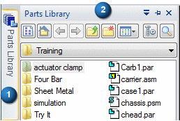
In the following instructions you will work with information in the Parts Library pane.
Set the Parts Library folder
-
On the Parts Library tab, click the arrow
 on the right side of the Look In control and then browse to the QY CAD Training folder.
The default location of the QY CAD Training folder is:
C:/Program Files/UDS/QY CAD 2022/Training
However, your system administrator may have chosen a different location.
-
Similar to Windows Explorer, you can define how you want to view the files listed in the Parts Library: Large Icons, Small Icons, List, and Details.
On the Parts Library tab, click the Views button
 , and then choose Details.
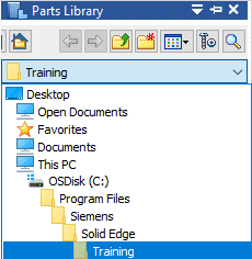
If the working folder on the Parts Library tab is not the QY CAD Training folder, do the following:
Place the rail part
![]()
To place a part into an assembly in QY CAD, you select the part from the file list in Parts Library and then drag it into the assembly.
-
In the file list area on the Parts Library tab, select the file named rail.par, hold down the left mouse button, drag the file into the assembly window, and then release the mouse button.
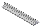
What is the relationship between this part and the rest of the assembly?
The first part you place in an assembly becomes the base component. QY CAD places this part fixed, using a Ground relationship. No other relationships need to be applied to this part to fully position it in the assembly.
Using the Assembly PathFinder
-
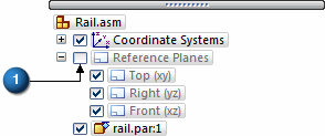
Click the check box (1) to turn on the display of the reference planes.
-
In PathFinder, position the cursor over the rail.par entry, but do not click.
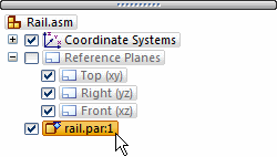
Notice that the rail display changes color in the assembly window.
-
Move your cursor away and notice that the display returns to the previous color.
![]()
In the next few steps, you will review the assembly using PathFinder, and then turn on and hide assembly reference planes.
Select the rail part
-
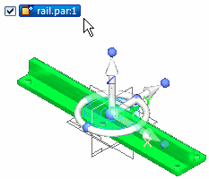
In PathFinder, position your cursor over the rail part again, then click, and move your cursor away.
Notice that the part color in the graphics window changes to a different color than in the previous step, and the Move command bar is displayed along with the steering wheel.
Also notice that when you select the part, the bottom pane of PathFinder displays the assembly relationships used to position the part. Since this is the first part in the assembly, the relationship symbol that is displayed is the ground relationship.
When working in assemblies, you can temporarily highlight parts using PathFinder, and you can also select them.
-
Press Escape.
Select the reference planes
-
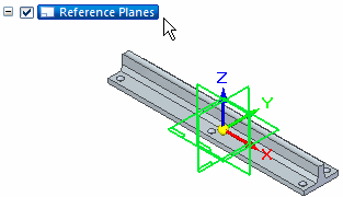
In PathFinder, position the cursor over the Reference Planes listing and click the left mouse button.
Notice that the three assembly reference planes change color in the Assembly window.
Hide the reference planes
-
In PathFinder, position the cursor over the check mark (1) adjacent to the Reference Planes entry, then click to hide the reference planes.
-
Turn off the Coordinate Systems display by clearing the check box.
The assembly reference planes are hidden in the Assembly window. Notice that the symbol in PathFinder for the Reference Planes listing has changed color.
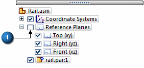
You can use the check boxes in PathFinder to display and hide assembly components.
The component entries in PathFinder also change color to indicate the current status of the assembly components.
If You Have Trouble Placing Parts
-
Press Escape to interrupt the part placement.
-
Use the Select command
 on the Home tab to select the part, and then press Delete to delete the part.
 -
Back up to the step where part placement begins and try again.
![]()
In the next few steps, place and position the bar part as shown. After placing the first part in an assembly, position additional parts using assembly relationships.
For the remainder of this tutorial, if you position a part incorrectly or lose your place while positioning a part:
Part Positioning Overview
![]()
To position parts in an assembly, apply a variety of assembly relationships.
For the bar part, apply the following relationships to fully position the bar with respect to the rail part.
-
Axial Align
-
Mate
-
Planar align
QY CAD provides a tool called FlashFit to apply each of these relationships, without having to specify the relationship type to use.
In the next few steps, use FlashFit to fully position the bar using an axial align, mate, and a planar align relationship.
Place the bar part
-
Click the Parts Library tab.
-
In the file list area on the Parts Library tab, select the file named bar.par, hold down the left mouse button, drag the file into the Assembly window, and then release the mouse button at the approximate position shown in the top illustration.
The bar part is placed into the assembly at the position where you released the mouse button.
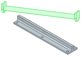
When you place a second part into an assembly, QY CAD displays the Place Part command bar.
![]()
Review the part placement options
-
On the Assemble command bar, click the Options button
 .
. -
On the Options dialog box, ensure that the options on your computer match the illustration.
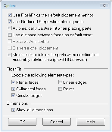
The FlashFit option allows you to specify what types of faces you want FlashFit to recognize.
For this tutorial, and most part positioning scenarios, the FlashFit settings shown work well.
Align the bar part in the rail part
-
On the Assemble command bar, in the Relationship Types list, the FlashFit option
 should be active.
Use FlashFit to apply an axial align relationship between a cylindrical face on the bar part and a cylindrical face on the rail part.
Tip:When two cylindrical faces are axially aligned, they are oriented so that they are coaxial.
![]()
Select the cylindrical face to align
-
In the Assembly window, position the cursor over the cylinder that comprises the body of the bar, at the approximate position shown in the illustration.
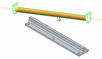
Depending on your computer settings, a message may display adjacent to the cursor.
Note:Use the Applications menu→Settings→Options→Helpers tab on the dialog box to specify whether a message displays, and how much information is contained in the message.
-
Click to select the cylindrical face shown.
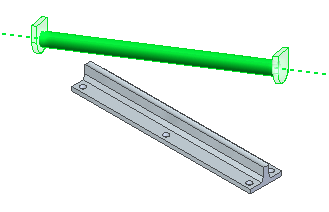
-
Align the axis of this cylindrical face with the axis of the top face of the rail, which is a partial cylinder.
When you select faces for the first assembly relationship, QY CAD repositions the part you are placing based on the approximate positions on the faces you select on the placement part and the part in the assembly.
Select the cylindrical face on the rail part
![]()
-
Select the partial cylindrical face on the rail part at the approximate position shown in the illustration.
Observe the result
![]()
The axial align relationship repositions the bar part in the assembly.
Because only one assembly relationship is applied so far, the position of the bar part might be different than the illustration.
In the next few steps, apply a mate relationship.
Fit the window
Commands for adjusting the contents of the graphic window are located at the bottom-right side of the QY CAD application window.
![]()
-
Click the Fit button
 to fit the contents of the view to the graphics window.
Mate the bar to the rail
![]()
Using FlashFit, the next relationship to apply is a mate relationship.
A mate relationship positions a part by orienting two planar faces so that they face each other.
Mated faces can touch or be offset from each other.
Use QuickPick to select the planar face on the bar
-
In the graphics window, move the cursor slowly over the bar part and notice how the faces and edges of the bar highlight.
-
Position the cursor over the face shown highlighted in the illustration. Stop moving the mouse for a moment, and notice that the cursor image changes to indicate that multiple selections are available. Also notice that the cursor image indicates which button to click to display the QuickPick list
 .
. -
Right-click and the QuickPick list displays. Move the cursor over the different entries in QuickPick, and notice that different elements of the model highlight. Use QuickPick to select the element desired, the first time, without having to reject unwanted elements.
-
Use QuickPick to highlight the planar face shown in the illustration, and then left-click to select it.
![]()
Select the mating face of the rail part
-
Use QuickPick to select the face at the left end of the rail, as shown in the illustration.
-
Right-click to display QuickPick.
-
Left-click to select an element within QuickPick.
-
![]()
Observe the result
![]()
The mate relationship repositions the bar part in the assembly.
Although the bar part appears correctly positioned on the rail, no relationship prohibits the bar from pivoting about the cylindrical faces aligned earlier.
In the next steps, use FlashFit to apply a planar align relationship to fully position the bar.
Select the aligning face on the bar
![]()
-
Use QuickPick to select the planar face shown.
Select the aligning face on the part in the assembly
![]()
-
Use QuickPick to select the planar face shown in the illustration.
Observe the result
![]()
The bar is now fully positioned in the assembly.
Notice that the Assemble command bar is dismissed.
Use PathFinder to review the assembly relationships
-
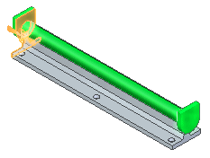
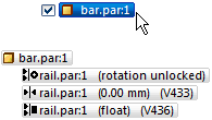
In PathFinder, click the bar.par:1 entry.
Notice that the relationships applied display in the bottom pane of PathFinder.
-
Pass the cursor over each of the relationship listings, but do not click.
Notice in the assembly window, that the faces used to apply the relationships highlight.
Later in the tutorial, learn how to edit an assembly relationship.
Save and close the assembly
-
Save the file. Click the Application button
 . On the Application menu, click Save.
 -
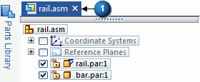
Close rail.asm by clicking the X (1) above the assembly window.
![]()
© 2021 UDS