Create the final assembly
Creating the final assembly
In this activity you will learn to construct the final assembly using the subassemblies you already created.
Launch the Create the final assembly.
Create the final assembly
-
Create a new assembly.
-
On the Application menu, click New→ISO Metric Assembly.
-
Click Iso Metric Assembly.asm to create a new assembly based on the ISO template, and then click OK.
![]()
In the next few steps, create the final assembly using the subassemblies created earlier.
This tutorial uses metric units of measure. If English units were selected during QY CAD installation, select a metric template. On the Application menu→New→New dialog box, click the ISO Metric template and then select iso metric assembly.asm. Click OK.
Place the base part in the assembly
-
Click the Parts Library tab.
-
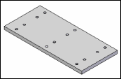
In the file list area on the Parts Library pane, select the file named base.par, hold down the left mouse button, drag the file into the assembly window, then release the mouse button.
![]()
Use PathFinder to hide the assembly reference planes
![]()
-
Ensure the Reference Planes and Coordinate Systems entries in PathFinder are hidden.
Save the assembly
![]()
-
Click Save
 , and on the Save As dialog box, save the assembly in the Training folder as slider.asm.
Place the rail subassembly in the final assembly
-
Click the Parts Library tab.
-
In the file list area on the Parts Library tab, select the file named rail.asm, hold down the left mouse button, drag the file into the Assembly window, then release the mouse button at the approximate location shown.
The rail assembly is placed in the Assembly window.
![]()
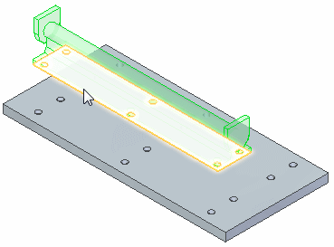
Select the face on the rail part to mate
-
In the graphics window, use QuickPick to select the bottom face on the rail, as shown in the illustration.
If the face on the rail cannot be selected...
When placing subassemblies, the current computer settings may require that the part that contains the face be activated first.
To activate the part and select the face, do the following:
-
On the Assemble command bar, click the Activate Part button
 .
. -
In the graphics window, select the rail part, then select the face.
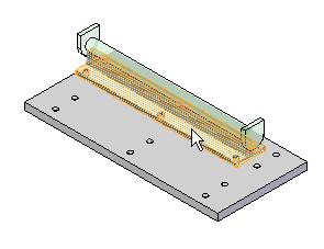
For more information, see the Placing Parts in Assemblies QY CAD Help topic.
Select the mating face on the base part
![]()
-
In the graphics window, use QuickPick to select the top face on the base, as shown.
Remember, if the top face highlights, bypass QuickPick and left-click to select the face.
Observe the result
![]()
The rail subassembly is repositioned in the assembly such that the bottom face of the rail is coplanar with the top face of the base.
The position of the rail subassembly may be different than the illustration.
In the next steps, apply an axial align relationship between cylindrical faces in the rail and base parts.
Fit the view
![]()
Use FlashFit to apply an axial align relationship between cylindrical faces on the rail and base. This will be easier to do if more of the model can be seen.
Commands for adjusting the contents of the graphic window are located at the bottom-right side of the QY CAD application window.
-
Click the Fit button
 to fit the contents of the view to the graphics window.
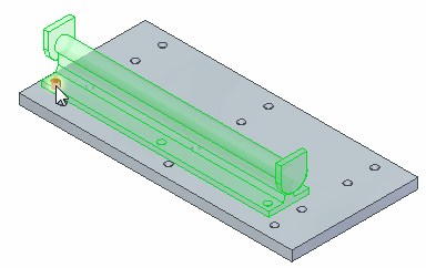
Select the cylindrical face to align on the rail part
-
Use QuickPick to select the cylindrical axis on the rail shown.
Select the cylindrical face to align on the base part
![]()
-
Select the cylindrical axis on the base shown.
Observe the result
![]()
The cylindrical faces on the rail and base are axially aligned.
Although the rail subassembly appears correctly positioned on the base, no relationship prohibits the rail from pivoting about the cylindrical faces just aligned.
In the next steps, apply another axial align relationship to fully position the rail subassembly.
Select the cylindrical face to align on the rail part
![]()
-
Select the cylindrical axis on the rail shown.
Select the cylindrical face on the base part
![]()
-
Select the cylindrical axis on the base shown.
Observe the result
![]()
The rail subassembly is now fully positioned with respect to the base part.
Place another rail subassembly
-
Click the Parts Library tab
 .
. -
In the file list area on the Parts Library tab, select the file named Rail.asm, hold down the left mouse button, drag the file into the Assembly window, then release the mouse button at the approximate location as shown in the illustration above.
The rail assembly is placed in the Assembly window.
![]()
Use FlashFit to apply a mate relationship between the bottom face of the rail and the top face of the base.
Select the face to mate on the rail part
![]()
-
Use QuickPick to select the bottom face of the rail, as shown.
Select the mating face on the base part
![]()
-
Use QuickPick to select the top face on the base, as shown.
Observe the result
![]()
The rail subassembly is repositioned in the assembly such that the bottom face of the rail is coplanar with the top face of the base.
In the next steps, apply an axial align relationship between cylindrical faces in the rail and base parts.
Fit the view
![]()
-
Click the Fit
 to fit the contents of the view to the graphics window.
Use FlashFit to apply an axial align relationship between cylindrical faces on the rail and base.
Select the cylindrical face on the rail
![]()
-
Select the cylindrical axis on the rail shown.
Select the cylindrical axis on the base part
![]()
-
Select the cylindrical axis on the base shown.
Observe the result
![]()
The cylindrical faces on the rail and base are axially aligned.
Again, although the second rail subassembly appears correctly positioned on the base, no relationship prohibits the rail from pivoting about the cylindrical faces you just aligned.
In the next steps, apply another axial align relationship to fully position the rail subassembly.
Select the cylindrical face to align
![]()
-
Use QuickPick to select the cylindrical axis on the rail shown.
Select the cylindrical axis on the base part
![]()
-
Select the cylindrical axis on the base shown.
Observe the result
![]()
The second rail subassembly is fully positioned in the assembly.
Save the assembly
![]()
-
Click Save
 .
.
Place the plate subassembly in the final assembly
-
Ensure the Parts Library tab
 displays.
 -
In the file list area on the Parts Library tab, select the plate.asm file, hold the left mouse button down, and drag the file into the assembly window.
-
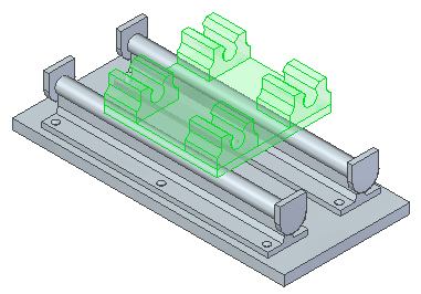
Drop the plate subassembly in the approximate position shown. The plate subassembly is positioned approximately as shown.
![]()
Evaluate the requirements
![]()
For this subassembly, mate the faces on the plate and base parts, as shown (1). These faces should not be coplanar—they will be parallel, but offset from one another.
Rather than specifying an offset distance, use a floating offset.
When setting the Floating Offset option, the offset value is determined by another relationship applied. In this case, apply an axial align relationship to control the offset value (2).
Specify a floating offset
![]()
-
On the Assemble command bar, on the Offset Type drop list, click the Floating Offset button. This setting allows the mating faces to take on whatever offset value is appropriate to satisfy the axial align relationship applied later.

Select the face to mate on the plate part
![]()
-
Select the face on the plate shown in the illustration.
If the face on the plate cannot be selected...
To activate the part and select the face, do the following:
-
On the Assemble command bar, click the Activate Part button
 .
. -
In the assembly window, select the plate part, then select the face.
Select the mating face on the base part
![]()
-
Select the top face of the base, as shown.
Flip the plate subassembly
![]()
The plate subassembly is positioned in the assembly similar to the top illustration.
-
On the Assemble command bar, click the Flip button
 to change the planar align relationship to a mate relationship.
The plate subassembly is repositioned similar to the illustration.
![]()
Select the cylindrical axis to align on the block part
![]()
Apply an axial align relationship between cylindrical axes on the block part and the bar part.
-
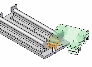
Use QuickPick to select the axis of the block shown.
If the face on the block cannot be selected...
To activate the part and select the face, do the following:
-
On the Assemble command bar, click the Activate Part button
 .
. -
In the assembly window, select the block part, then select the axis.
Select the cylindrical face on the bar part
![]()
-
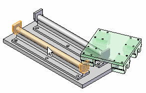
Select the face on the bar shown.
If the face on the block cannot be selected...
To activate the part and select the face, do the following:
-
On the Assemble command bar, click the Activate Part button
 .
. -
In the assembly window, select the bar part, then select the face.
Observe the result
![]()
Notice that aligning the block and bar has resulted in offsetting the mate relationship between the plate and base.
Because one more relationship is required, the plate subassembly may be positioned along the rail at a different position than shown.
Align the block part to the rail part
![]()
Apply a planar align relationship between a face on the block and a face on the rail. Also specify an offset distance for this relationship.
Select the face to align on the block part
![]()
-
Use QuickPick to select the face of the block shown.
Select the aligning face on the rail part
![]()
-
Use QuickPick to select the face of the rail shown.
Observe the result
![]()
The plate subassembly is fully positioned in the assembly.
In the next few steps, edit the offset value for the align relationship just applied.
Select the plate assembly
-
Click the PathFinder tab
 .
. -
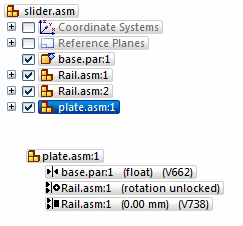
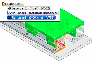
In the top pane of PathFinder, select the plate.asm entry as shown.
Notice that when selecting the plate subassembly in PathFinder, that the relationships applied display in the bottom pane. Also notice the various symbols used in PathFinder.
These symbols are used to designate the parts, subassemblies, relationships, and others used in the Assembly environment. To learn more about PathFinder, see the QY CAD Help topic titled PathFinder in Assemblies.
Select the planar align relationship in PathFinder
-
In the bottom pane of PathFinder, select the planar align relationship as shown.
In the Assembly window, notice that the faces used to position the plate subassembly highlight.
Edit the offset value for the relationship
-
On the Select command bar, click the Edit Definition button. The Assemble command bar
 is displayed.
 -
In the Offset Value box, type 100, then press Enter.

Notice that the plate subassembly adjusts its position to reflect the new offset value.
![]()
Save the assembly
![]()
-
Save the assembly.
Place the first bolt
-
Ensure the Parts Library tab
 displays.
 -
In the file list area on the Parts Library tab, select the socket4.par file, hold the left mouse button down, drag the file into the assembly window, then release the mouse button at the approximate position shown.

![]()
In the next few steps, place a bolt, and then create a pattern of bolts.
Use the Zoom Area command
-
At the bottom-right side of the QY CAD application window, click Zoom Area
 , then zoom in as shown in the illustration. This makes it easier to place the bolt.
 -
After resizing the view area, right-click to exit the Zoom Area command.
![]()
Insert the bolt into the rail
![]()
Use a different part positioning option to position the bolt.
-
On the Assemble command bar, in the Relationship Types drop list, click the Insert option, as shown.
The Insert option applies a mate relationship and an axial align relationship between the part being placed and a part in the assembly. The axial align relationship is placed using the Fixed option, which fixes the rotational orientation of the part.
If control is needed for the rotational orientation of the part, edit the axial align relationship later. The Insert option is very useful for assembling a cylindrical part, such as a bolt, into a hole.
The Insert option requires that all relationships are placed to only one part in the assembly. If the part being placed needs to be positioned with respect to more than one part in the assembly, place the relationships individually using FlashFit, or the Mate and Axial Align options.
Select the planar face to mate on the bolt
![]()
-
Select the planar face shown.
Select the planar face on the rail
![]()
-
Select the planar face shown.
Select the cylindrical face on the bolt
![]()
-
Select the cylindrical face shown.
Select the cylindrical axis on the rail
![]()
-
Select the cylindrical axis shown.
Observe the result
![]()
The bolt is inserted into the rail.
Fit the Assembly window
![]()
-
Click the Fit
 to fit the contents of the view to the graphics window.
In the next few steps, use the Pattern command to copy the bolt into the remaining holes in the rail.
Pattern the bolt
![]()
-
Choose the Home tab→Pattern group→Pattern command
 .
.
Use the Pattern command to copy a part in the assembly into a pattern. Define the pattern by selecting a pattern feature on a part in the assembly. The patterned parts are not positioned using assembly relationships, but are positioned using the selected pattern feature.
Select the bolt
-
Select the socket head bolt.
-
On the Pattern command bar, click Accept
 .
.
![]()
Select the part containing the pattern
![]()
-
Select the rail.
Select the feature pattern on the rail
![]()
-
Select the pattern of holes on the rail, as shown.
Select a reference position on the pattern
![]()
-
Select the hole on the rail where the first bolt was placed.
Finish the pattern
![]()
-
On the Pattern command bar, click Finish.
Place the remaining bolts
![]()
-
Optional step: Place the remaining bolts. Use the techniques learned earlier to insert a bolt in the other rail. Then pattern it into the remaining holes in the rail.
Save the final assembly
-
Save the assembly.
-
Close the file.
![]()
© 2021 UDS