Activity: Add driving dimensions
Add driving dimensions
In this activity, you will add more driving dimensions to control the behavior of the geometry you just created.
Launch the Activity: Add driving dimensions.
Make the Dimension layer the active layer
![]()
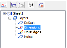
In the next few steps, add driving dimensions to control the size and position of the circle, as shown in the top illustration. First, make the Dimensions layer active.
-
On the Layers tab, double-click the Dimensions layer to make it the active layer.
Place a dimension to control the size of the circle
-
Choose Home tab→Dimension group→Smart Dimension
 .
. -
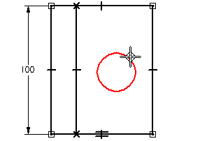
Position the cursor over the circle you drawn earlier, as shown in the illustration. When the circle highlights, click to select it.
-
Move the cursor to the approximate position shown in the bottom illustration, and then click to define the dimension location.

-
If the circle diameter is not 30 millimeters, on the value edit handle adjacent to the dimension, type 30, and then press Enter.
Select the Distance Between command
![]()
-
Choose Home tab→Dimension group→Distance Between
 .
. -
On the command bar, ensure that the Horizontal/Vertical option is selected.

Select the elements for dimensioning
-
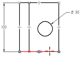
Position the cursor over the line shown in the following illustration, and then click to define the dimension origin.
-
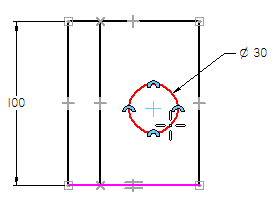
Position the cursor over the circle, as shown in the following illustration. When the circle highlights, click.
Define the dimension orientation
-
Position the cursor, as shown in the illustration, and click to position the dimension.
The dimension value may be different than the illustration.
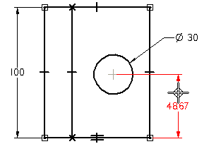
-
On the value edit handle adjacent to the dimension, type 50, and then press Enter.

-
Right-click to restart the Distance Between command.
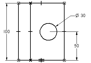
Move the cursor around the drawing and notice that the dimension orientation changes to indicate that multiple solutions are available.
If the value edit handle does not display and the dimension value is shown in dark cyan rather than in black, then a driven dimension was created instead of a driving dimension. This can happen if the geometry selected already has a geometric relationship defined for it.
This activity requires a driving dimension. If a driven dimension was created, delete the dimension and start over using the Distance Between command.
Select more elements for dimensioning
-
Position the cursor over the line shown in the illustration, and then click to define the dimension origin.
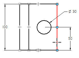
-
Position the cursor over the circle, as shown in the bottom illustration. When the circle highlights, click.
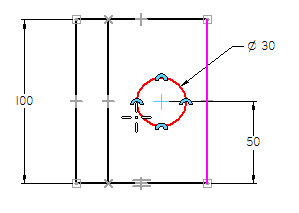
Define the dimension orientation
-
Position the cursor, as shown in the illustration, and click to position the dimension.
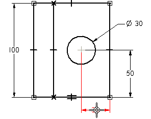
-
On the value edit handle adjacent to the dimension, type 30, and then press Enter.
-
Right-click to restart the Distance Between command.
![]()
Save the file
![]()
 On the Quick Access toolbar, choose Save to save the work done so far.
![]()
| Activity: Use relationships to align geometry |
© 2021 UDS