Activity: Add dimensions, more relationships, and hidden lines
Add dimensions, more relationships, and hidden lines
In this activity you will:
-
Add a driving dimension and a geometric relationship to the rectangle you just drew.
-
Place a dimension on a separate layer.
-
Add geometry.
-
Add hidden line geometry.
Launch the Activity: Add dimensions, more relationships, and hidden lines.
Make the Dimension layer the active layer
In the next few steps, add a driving dimension and a geometric relationship to the rectangle just drawn. To place the dimension on a separate layer, make the Dimensions layer active.
-
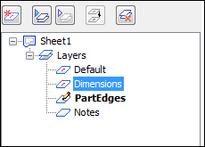
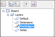
On the Layers tab, double-click the Dimensions layer entry to make it the active layer.
Place a driving dimension on the rectangle
-
Choose Home tab→Dimension group→Smart Dimension
 .
. -
On the Smart Dimension command bar, ensure that the Driving option
 is selected.
 -
Position the cursor over the vertical line on the rectangle, as shown in the illustration. When the line highlights, click to select it.

-
Move the cursor to the left of the rectangle, as shown below, and then click to define the dimension location.
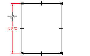
Notice that the dimension value displays on the value edit handle adjacent to the dimension.

-
On the value edit handle, type 100, and then press Enter.
Notice that the display value and the rectangle height update. The dimension placed is a driving (locked) dimension.
Driving dimensions control, or drive, the elements on which they are placed. Use the Lock button to create a driving dimension.
When typing values in an edit handle box, the unit type does not have to be entered, such as mm or degrees.
Constrain the rectangle width
-
Choose Sketching tab→Relate group→Equal
 .
. -
Position the cursor over the horizontal line in the rectangle, as shown in the illustration. When the line highlights, click to select it.
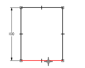
-
Move the cursor to the line in the front view, as shown in the bottom illustration, and then click to select it.
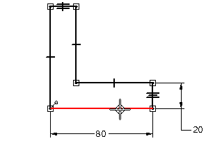
Notice that the rectangle width changes to be equal to the length of the second line selected. The equal relationship is an example of a geometric relationship. Geometric relationships are used to control the size, shape, or position of one or more 2D elements. They are also sometimes referred to as geometric constraints.
Because there is already a driving dimension in the front view that defines the part width, use an equal relationship to control the width of the rectangle drawn for the top view.
Geometric relationship symbols are not placed on layers. Control the display of geometric relationship symbols using the Relationships Handles command. This option was verified earlier in the tutorial.
Later, this option will be cleared to hide the relationship symbols.
Make the PartEdges layer the active layer
In the next few steps, finish drawing the elements which represent the part edges. Draw a circle and some more lines.
-
On the Layers tab, double-click the PartEdges layer entry to make it the active layer.
Draw a circle
-
Choose Sketching tab→Draw group→Circle By Center Point
 .
. -
On the Circle command bar, in the Diameter box, type 30, and then press Enter.

-
Position the cursor approximately as shown, and then click to place the circle.
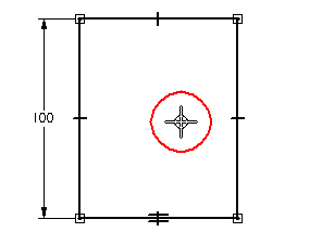
The circle will be positioned later using driving dimensions.
Draw another line
-
Choose Sketching tab→Draw group→Line
 .
. -
Position the cursor over the line shown in the illustration, such that it is approximately aligned with the line shown in the front view.
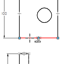
-
When the point on relationship indicator
 displays adjacent to the cursor, click.
 -
Position the cursor over the line shown in the illustration below, and when the point on
 and vertical
  relationship indicators display adjacent to the cursor, click.
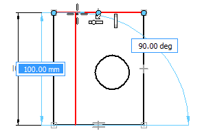
-
When finished drawing the line, right-click to restart the Line command.
Geometric relationships will be used later to precisely position this line.
Start a hidden line
-
On the command bar, from the Style list, select the Hidden option.

-
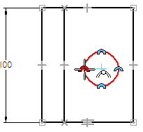
First, position the cursor over the circle approximately as shown in the illustration, but do not click.
-
When the silhouette point relationship indicator displays adjacent to the cursor
 , move the cursor down to the line shown in the illustration below.
Notice that a dashed line is displayed between the circle highlighted and the current cursor position. This indicates that the cursor is precisely aligned with the edge of the circle.
-
When the point on relationship indicator
 displays adjacent to the cursor, click to start the line.
In the next few steps, draw two hidden lines in the front view that represent the edges of the circle in the top view. Use IntelliSketch to help position the lines.
![]()
Finish the hidden line
![]()
-
Position the cursor over the line shown, and when the point on relationship
 and vertical
  indicators display adjacent to the cursor, click to finish the line.
If the second point wants to jump to the midpoint, there are two ways to work around it.
-
Hold the Shift key to increment the value in the angle edit box to -90 degrees while locating the point.
-
On the Home tab→IntelliSketch group, clear the Mid point indicator.

If this method is used, be sure to check the box when finished drawing the line.
-
-
When finished drawing the line, right-click to restart the Line command.
Draw another hidden line
-
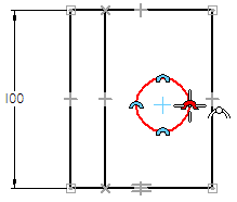
First, position the cursor over the edge of the circle, as shown below, but do not click.
-
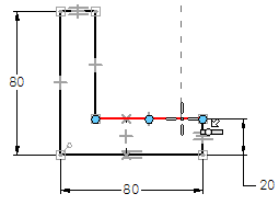
When the silhouette point relationship indicator displays, move the cursor down to the line on the front view, as shown below.
-
When the point on relationship indicator displays, click to start the line.
-
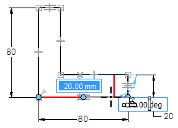
Move the cursor to the bottom line, and when the point on and vertical relationships indicators display, click to finish the line, as shown below.
-
When finished drawing the line, right-click to restart the Line command.
Use the same technique you used in the previous steps to draw another hidden line.
Save the file
![]()
-
On the Quick Access toolbar, choose Save to save the work done so far.

© 2021 UDS