Activity: Use relationships to align geometry
Use relationships to align geometry
![]()
In this activity, you will:
-
Use geometric relationships to align the elements between the views. For example, the vertical lines in the top view must stay aligned with corresponding lines in the front view.
-
Align the hidden lines in the front view with the circle in the top view using vertical and tangent relationships.
Launch the Activity: Use relationships to align geometry.
Using relationships to maintain symmetry
![]()
In addition to specifying that a line remains horizontal or vertical, also use a horizontal/vertical relationship to specify that one element remains horizontally or vertically aligned with respect to another element.
Use a vertical relationship to specify that the endpoints of vertical lines in the top view stay vertically aligned with the endpoints of the vertical lines in the front view.
This ensures that the vertical lines in the top view remain orthographically aligned to their corresponding elements in the top view, regardless of their size.
This technique is a powerful tool that can be used in many situations.
Apply a vertical relationship
-
Choose Sketching tab→Relate group→Horizontal/Vertical
 .
. -
Position the cursor as shown in the following illustration, and when the endpoint relationship indicator displays, click.
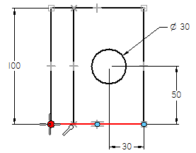
-
Position the cursor as shown in the following illustration, and when the endpoint relationship indicator displays, click. The line position updates.
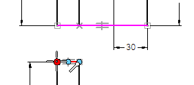
Apply another vertical relationship
-
Position the cursor as shown in the following illustration, and when the endpoint relationship indicator displays, click.
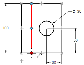
-
Position the cursor as shown in the following illustration, and when the endpoint relationship indicator displays, click. .
The line position updates.
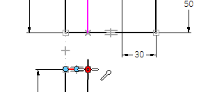
The Horizontal/Vertical command should still be active.
Apply a tangent relationship
-
Choose Sketching tab→Relate group→Tangent
 .
. -
Position the cursor on the hidden line, as shown in the illustration, and when the line highlights, click.
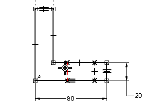
-
Position the cursor as shown in the bottom illustration, and when the circle highlights, click.
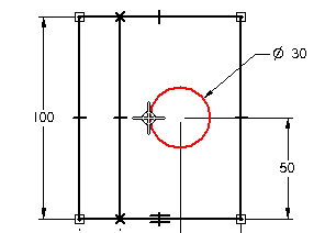
The hidden line position in the front view updates to be tangent to the circle in the top view.
Apply another tangent relationship
-
Position the cursor as shown in the illustration, and when the line highlights, click.
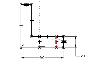
-
Position the cursor as shown in the bottom illustration, and when the circle highlights, click.
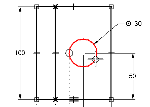
The Tangent command is still active.
The hidden line position in the front view updates to be tangent to the circle in the top view.
Observe the results
![]()
Take a few moments to observe the tangent relationships you applied.
If the views do not match the illustration, use the Select command to delete the tangent relationships, and then apply them again.
Hide the geometric relationships
The steps to place dimensions and apply geometric relationships are finished.
-
Choose Sketching tab→Relate group→Relationship Handles to hide the relationship indicators.
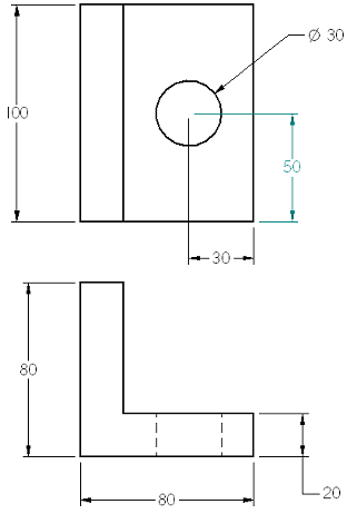
In the next few steps, place centerline and center mark annotations.
Place a centerline
![]()
-
Choose Home tab→Annotation group→Centerline
 .
. -
On the Centerline command bar, ensure the By 2 Lines option is set.

In the next step, place a centerline on the hidden lines that represent the hole in the front view, as shown in the illustration.
Select the elements for the centerline
-
Position the cursor over the hidden line shown in the illustration and click.
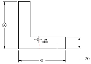
-
Position the cursor over the hidden line shown in the bottom illustration and click.
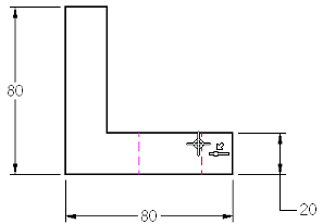
Place a center mark
![]()
-
Choose Home tab→Annotation group→Center Mark
 .
. -
On the command bar, set the Projection Lines option
 .
.
In the next step, place a center mark on the circle in the top view.
Select the element for the center mark
-
Click the circle in the top view, as shown in the illustration.
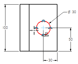
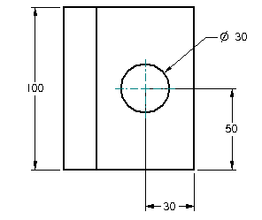
The center mark is added as shown below.
Rename a variable
-
Choose Home tab→Select group→Select.

-
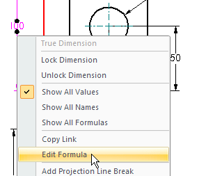
Position the cursor over the 100 millimeter dimension in the top view, and then right-click to display the shortcut menu.
-
On the shortcut menu, click Edit Formula to display the Edit Formula command bar.
-
On the Edit Formula command bar, in the Name box, type Length, and then press Enter.

-
To finish renaming the variable, press Enter a second time, or click Accept (the green check mark)
 on the command bar.
In the next few steps, define new names for two of the dimensions placed and use these names to define a formula between the dimensions.
This allows a change to the the length of the part, while keeping the circle centered on the part.
Rename another variable and create a formula
-
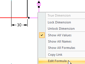
Right-click the 50 millimeter dimension to display the shortcut menu.
-
On the shortcut menu, click Edit Formula to display the Edit Formula command bar.
-
On the Edit Formula command bar, in the Name box, type HoleLoc, and then press Enter.

-
The cursor moves to the Formula box.
-
On the sheet, click the 100 millimeter dimension. Notice that the dimension name, Length, is pasted into the Formula box.
-
In the Formula box, type /2.
-
When the entire formula is as shown below, press Enter a second time, or click Accept (the green check mark).

This specifies that the HoleLoc dimension should always be one half the value of the Length dimension (HoleLoc=Length/2).
Edit a dimension
-
Verify the Select command is still active.

-
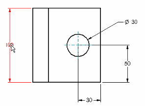
Click the 100 millimeter dimension value, as shown in the illustration.
-
In the value edit handle adjacent to the dimension, type 90, and then press Enter.
Notice that the dimension that controls the circle position also updates, and the hole remains centered on the part.
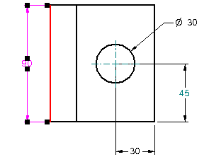
Edit the dimension that controls the part length in the top view. Because a formula was created a formula that associates the hole position to the part length, the hole will remain centered on the part.
The dimension value, 45, is displayed in dark cyan. This indicates the dimension value is driven by its relationship to another element. In this case, it is related to the height dimension by a formula.
Save the file
![]()
-
In the viewing commands group at bottom-right of the window, choose Fit to fit the view.

-
On the Quick Access toolbar, choose Save to save the work.

© 2021 UDS