Activity: Draw with layers, relationships, and IntelliSketch
Draw with layers, relationships, and IntelliSketch
![]()
In this first activity, you will learn:
-
How to set options for 2D geometric relationships.
-
How to use the Layers tab.
-
How to use the IntelliSketch tool.
-
How to draw a 2D shape.
Launch the Activity: Draw with layers, relationships, and IntelliSketch.
Open the activity draft file
-
Open ...\Program Files\UDS\QY CAD 2022\Training\sbddadr.dft.
-
Click the Application button.

-
On the Application menu, choose the Save As command.
-
In the Save As dialog box, save the dft file to a new name or location so that other users can complete this activity.
This tutorial refers to command locations in the QY CAD Draft environment. To find the equivalent location in QY CAD 2D Drafting, type the command name in Command Finder, which is located in the status bar at the bottom of the application window.

Verify the relationship handle settings
![]()
This tutorial refers to commands on the Sketching tab in the QY CAD Draft environment. In QY CAD 2D Drafting, look for these commands on the Home tab, instead.
-
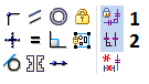
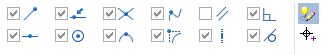
On the Sketching tab, in the Relate group, ensure the following options are set:
When these options are set, they are shaded blue.
-
Maintain Relationships (1): This option remembers the application of geometric relationships during 2D element creation and editing. For example, when a horizontal relationship is applied to a line, the line remains horizontal during edits.
-
Relationship Handles (2): This option displays the relationship handles on the 2D elements, as shown in the illustration at the top of this page.
Learn more about these options later in this tutorial.
-
Display the Layers tab

-
Choose the Home tab→Select group→Select command.
 Note:
Note:The Select command is the default command.
-
Find and click the Layers tab.

The Layers tab may be located along the left side of the application window.
-
On the Layers tab, notice that several existing layer names display. These layer names were created and saved for you.
In the next few steps, draw and place dimensions on several 2D elements. Use the Layers tab to control the active layer and which layers display.
Set the active layer
New elements created are placed on the active layer.
The active layer name appears in bold and is also indicated on the Layers tab by the active layer symbol ![]() .
.
-
If the active layer symbol does not display adjacent to the PartEdges layer, then double-click the PartEdges layer entry to make it the active layer.
Zoom in
![]()
-
On the bottom-right side of the application window, on the Viewing Commands toolbar, choose the Zoom Area command
 .
. -
Click once above and to the left of the area shown, and then click again below and to the right. The view zooms to the area enclosed by the rectangle.
-
Right-click to exit the Zoom Area command.
Draw a rectangle
![]()
-
Choose the Sketching tab→Draw group→Rectangle list→Rectangle by 2 Points
 .
.Use the Style option on the Rectangle command bar to control whether 2D elements are drawn using Visible, Hidden, or other types of commonly used line styles.
-
On the command bar, ensure that the Style option is set to Visible.
-
Position the cursor at point (1), as shown in the illustration at the top of the page, and click.
-
Move the cursor towards point (2) and notice that the edit boxes update to show the current width, height, and angle value. Also notice that these values are shown on the Width, Height, and Angle boxes on the command bar.
-
Move the cursor up and to the right until the Width value is approximately 80 mm, and the Height value is approximately 100 mm. Click to define point (2).
A rectangle consisting of two horizontal and two vertical lines displays. The four lines are also endpoint connected, which means that they stay connected when making changes. Learn more about this later.
-
Press Escape to exit the Rectangle by 2 Points command.
Observe the rectangle
![]()
Geometric relationships control how the sketch geometry reacts during modifications.
-
Notice that symbols representing geometric relationships display on the rectangle.

The symbols on the midpoint of the lines represent horizontal and vertical relationships.

The symbols on the endpoints of the lines represent end-point connect relationships.
These relationships were automatically applied based on the cursor position and the current IntelliSketch settings. Learn more about this in the next few steps.
-
When positioning the cursor over the symbols, they display in the Highlight color.
When modifying the rectangle sketch later, the lines will remain endpoint connected, and horizontal and vertical.
Learn more about IntelliSketch
-
Choose Sketching tab→IntelliSketch group→IntelliSketch.
The IntelliSketch dialog box displays.
-
Ensure the settings match the top illustration.
-
Take a few moments to review the options on the Relationships tab in the IntelliSketch dialog box. The Relationships tab defines which relationships are recognized by IntelliSketch while drawing a sketch.
Notice that the Endpoint and Horizontal or Vertical options are set. These options were used to automatically apply the relationships to the rectangle. Also notice that the options in the IntelliSketch group on the command ribbon can be used to set these options.
-
In the IntelliSketch dialog box, click OK.
Delete a line
Delete one of the lines, and then draw a replacement line. Use the Select command select elements, so they can be edited, copied, and deleted.
-
Verify the Select command is active.
-
Move the cursor over the lines in the sketch. Notice that the lines highlight as the cursor passes over them.
-
Position the cursor over the line shown in the illustration, and then click to select it.
Notice that:
-
The line color changes to the Select color.
-
The Line command bar displays, showing the length and angle of the line.
-
-
Press Delete.
The cursor must be positioned in the QY CAD window when pressing Delete.
The line is deleted from the sketch. Notice that the line, the horizontal relationship and the endpoint connect relationships were all deleted.
Start the Line command
![]()
-
Choose the Sketching tab→Draw group→Line command
 .
.
Draw a new line
-
Move the cursor to the end point of the line shown below, and when the endpoint relationship indicator
 displays adjacent to the cursor, click.
-
Move the cursor to the end point of the line shown in the bottom illustration, and when the endpoint relationship indicator
displays adjacent to the cursor, click.
-
Right-click to restart the Line command.
Observe the results
![]()
Take a few moments to observe the line just drawn.
The new line should have endpoint connect relationships at both ends, and a horizontal relationship near its midpoint.
-
If the sketch does not match the illustration, use the Select command to delete the line, and then use the Line command to draw another line.
Save the file
-
On the Quick Access toolbar, choose Save to save the work you have done so far.

© 2021 UDS