Activity: Detail the front view
Detail the front view
In this activity, use the Retrieve Dimensions command to quickly place model dimensions on a drawing view. Also use the Distance Between, Angle Between, and Smart Dimension commands to add missing dimensions in the Front view. Adjust dimension positions, and add callouts, feature control frames, and datum frames.
Launch the Activity: Detail the front view.
Retrieve dimensions
-
Choose Home tab→Dimension group→Retrieve Dimensions
 .
. -
Click the Front view (center-left).
The dimensions are copied from the model to the drawing view, as shown below.
-
Click the Top view (top-left) to retrieve its dimensions.
-
Press Escape to end the command.
Your drawing sheet should look like the one shown below.
Select and clear options on the Retrieve Dimensions command bar to control the types of dimensions that you retrieve, as well as whether annotations are retrieved.
Zoom in on the front view
-
Click the Zoom Area button
 .
. -
Click above and to the left of the Front view, then drag the cursor below and to the right of the view, and click again.
-
Right-click to exit the command.
Place dimensions on the front view
![]()
-
Click the dimension line of linear dimension 51, and then press Delete. Do not click the dimension text.
-
Use the same technique to delete angular dimension 60 degrees.
-
Choose the Home tab→Select group→Select command. Position the cursor on the radial 21 dimension text. When the locate cursor is displayed
 , press and hold the left mouse button while dragging the dimension closer to the part.
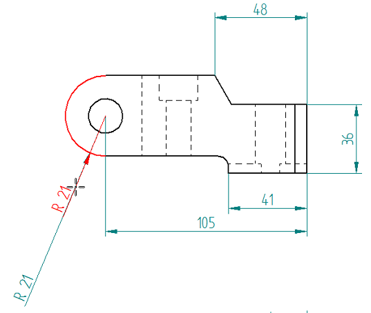
-
Place a linear dimension between elements:
-
Choose the Distance Between command
 .
. -
Place the cursor on the center of the hole, and when the center point indicator appears
 , click. (1)
 -
Select the part edge at the top of the notch. (2)
-
Move the cursor to the left to position the dimension as shown below, and then click to place it.
-
Press Escape.
-
-
Place an angular dimension between the two top faces of the part.
-
Choose Home tab→Dimension group→Angle Between
 .
. -
Select the line representing the angled face at position (1), as shown in the following illustration.
-
Select the line representing the lower, notched face at position (2), as shown in the following illustration.
-
Click to place the dimension as shown below, and then press Escape to end the Angle Between command.
-
-
Place a radius dimension at the bottom of the part.
-
Choose the Smart Dimension command
 .
. -
Position the cursor so the radius highlights, and then click.
-
Position the dimension as shown below, and then click.
-
Press Escape.
-
Use the Distance Between, Angle Between, and Smart Dimension commands to add missing dimensions in the Front view.
The dimensioned Front view should match the illustration below.
![]()
Adjust the position of dimensions
![]()
-
Choose the Select command if it is not already active.
-
Adjust the position of a dimension in the Front view.
-
Place the cursor on the 48 dimension line.
-
-
Press the left mouse button, and then drag the dimension closer to the part.
-
Adjust the position of dimension text in the Front view.
The Select command should still be active. The dimension should still be highlighted.
-
Place the cursor on the 48 dimension text, so that the locate cursor is displayed.
-
Press the left mouse button, and then drag the dimension text outside the extension lines.
Observe the horizontal and vertical dashed lines that appear at the original dimension text position. Snap the dimension text to the intersection of these lines to move the dimension text back to its original position.
-
-
Adjust the position of another dimension in the Front view.
The Select command should still be active.
-
Place the cursor on the 105 dimension line (not on the dimension text) to display the locate cursor.

-
Click+drag dimension 105 so that it is positioned above the part.
-
Adjust the position of dimensions, dimension text, and dimension arrows. Cursor placement determines how dimensions are manipulated.
The Front view should match the illustration below.
![]()
The dimension arrows can also be moved outside the extension lines. Just drag either of the dimension arrows; the second arrow follows the first.
Use a callout to extract hole size
![]()
-
Choose Sketching tab→Annotation group→Callout
 .
. -
In the Callout Properties dialog box:
-
Click the Diameter button. (1)
-
Click the Size button. (2)
-
Click OK to continue.
-
-
On the command bar, select Leader and Break Line.

-
Place the callout.
-
In the Front view, click the hole.
-
Move the cursor so that the callout is positioned as shown in the illustration at the top of the page, and then click.
-
-
Press Escape to end the command.
Extract the size of the hole in the Front view using the Callout command.
Place a datum frame
-
Choose Home tab→Annotation group→Datum Frame
 .
. -
On the command bar, do the following:
-
Clear the Leader and Break Line options.
-
In the Text box, type A.

-
-
In the drawing view, position the cursor on the line at the top of the notch, as shown. When the midpoint indicator appears, click the line.
-
Move the cursor to the right of the part, and click to place the datum frame.

-
Press Escape.
-
Hold the Shift key and click the Fit button
 .
.This brings everything within the drawing border back into view, but not the drawing sheet itself.
Use the Datum Frame command to add datum frame A to the Front view. When finished, the Front view should match the one above.
Place a feature control frame
![]()
-
Choose Home tab→Annotation group→Feature Control Frame
 .
. -
In the Feature Control Frame Properties dialog box, in the first text box in the Content section, create the frame shown in the illustration below.
Follow these guidelines:
-
Click in the Content box at the location for the value to appear, and then type it.
Example:For this tutorial, type the values 0.3, B, A, and C.
-
Press the Spacebar to add spaces.
-
Click the appropriate buttons to generate the symbols.
-
Click the Divider button
 to insert a vertical separator between symbols and values.
The Preview area at the right side of the dialog box shows how the annotation will appear on the drawing.
-
-
Place the feature control frame without a leader below the hole diameter callout by doing the following:
-
Click OK to close the Feature Control Frame Properties dialog box.
-
Clear the Leader option on the command bar.
-
Click the hole callout text to create an association with the feature control frame, and then position the feature control frame approximately as shown below. Click to place it.
-
-
Press Escape.
Use the Feature Control Frame command to define the required tolerance on a feature. Tolerance is specified by datums, which are letters (or characters) that reference other part features.
When finished, the Front view should match the one at the top of this page.
Insert reference text
-
Double-click the feature control frame to edit it.
-
In the Feature Control Frame Properties dialog box, on the General tab, do the following:
-
Place the cursor to the right of the A in the Content box, and press the Backspace key to delete it. Take care not to delete the divider between the boxes.
-
Click the Reference Text button
 .
.The Select Reference Text dialog box is displayed.
-
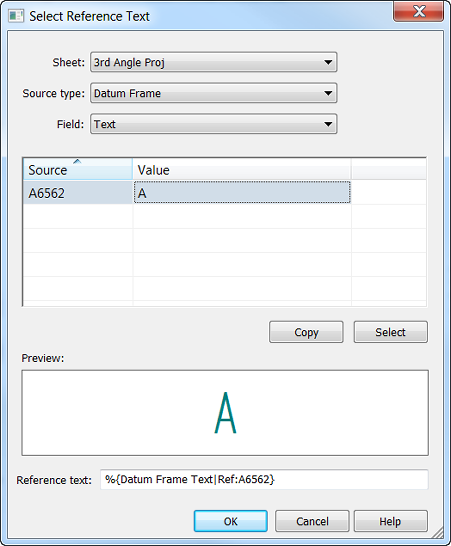
In the Select Reference Text dialog box, do the following
-
From the Source type list, select Datum Frame.
-
From the Field list, select Text.
At this point, the Source and Value columns are populated with a single entry, because there is only one datum frame on this sheet in the active document. The object ID seen in the Source column may be different than the one shown at the top of this page.
-
Click either cell in the table grid, and then click the Select button.
Notice that:
-
A preview of the reference text is shown in the Preview box.
This is the content that will be inserted into the feature control frame. In this example, the preview is the same as the value. In many cases, these are different.
-
Information is displayed in property text format in the Reference text box at the bottom of the dialog box.
-
-
Click OK to close the Select Reference Text dialog box.
Observe that the reference text was inserted into the feature control frame Content box, at the position of the cursor.
-
Click OK to close the Feature Control Frame Properties dialog box.
-
-
Use the Select Reference Text dialog box to select and insert text from one annotation or drawing view into another annotation. The information is updated automatically in the referencing annotation when it is changed in the source annotation or drawing view.
Update the feature control frame to insert a reference to the datum in the datum frame annotation.
To see how reference text works:
-
Double-click the datum frame to open the Datum Frame Properties dialog box, and then change the datum letter to something other than A. Click OK to close the Datum Frame Properties dialog box.
-
Observe that the feature control frame updates to show the letter typed.
The annotations referenced do not have to be on the same sheet in the document. Use the Sheet list at the top of the Select Reference Text dialog box to select a different sheet to reference text in any datum frame, datum target, callout, or balloon. Text in a drawing view can also be referenced.
-
Change the datum frame letter back to A.
Using QuickPick to select elements
If there is trouble selecting exactly what is wanted among multiple elements, use QuickPick. When seeing the QuickPick prompt displayed near the cursor, right-click.
![]()
Then, from the QuickPick list, click the element to select. If there are multiple elements with the same name, such as Line, move the cursor down the list and watch as each one highlights in the window.
The active command continues uninterruptedly, using the element selected.
Save the file
The drawing should now look like the image above.
-
On the Quick Access toolbar, choose the Save command to save the work.

© 2021 UDS