Activity: Detail the section view
Detail the section view
![]()
In this activity, detail a section view. Place centerlines and dimensions.
Launch the Activity: Detail the section view.
Place centerlines in the section view
![]()
-
Zoom in on the section view:
-
Click the Zoom Area button
 , and size the area around the view with the caption Section B-B.
 -
Right-click to exit the Zoom Area command.
-
-
Verify the IntelliSketch setting for placing a centerline by choosing Sketching tab→IntelliSketch group→
 , and then ensuring that the Midpoint check box is checked.
 -
Place a centerline on the hole with a counterbore:
-
On the Sketching tab or the Home tab, choose Annotation group→Centerline
 .
. -
On the Centerline command bar, from the Placement Options list, click the By 2 Points option.

-
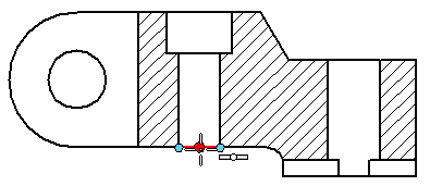
Move the cursor over the line at the bottom of the counterbore hole, and when the midpoint relationship indicator appears
 , click.
-
-
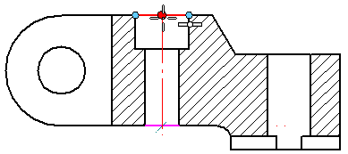
Click at the midpoint of the top of the hole to complete the centerline.
-
The Centerline command is still active to add another centerline:
-
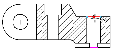
Move the cursor over the line at the bottom of the simple hole, and when the midpoint relationship indicator appears
 , click.
 -
Click at the midpoint of the top of the hole to complete the centerline.
-
-
Press Escape to end the command.
Add a centerline annotation to holes using the Centerline command.
The section view should look like the one at the top of the page.
For more relationships and dimensioning and drawing options, open the IntelliSketch dialog box and review the Relationships page. To open the dialog box, click the IntelliSketch button ![]() on the Sketching tab→IntelliSketch group.
on the Sketching tab→IntelliSketch group.
Place dimensions on the section view

-
Add a dimension between two elements:
-
Choose Home tab→Dimension group→Distance Between
 .
. -
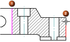
Select the inside edge of the part (1), and then select the outside edge of the part (2).
-
Move the cursor to position the dimension above the part, and then click to place it.
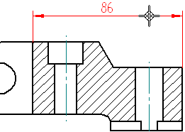
-
Right-click to restart the command, without exiting it.
-
-
Place a dimension that shows the depth of the notch using the still-active Distance Between command.
-
Select the line at the bottom of the notch.
-
Select the line at the top of the notch.
-
Position the cursor as shown below, and click to place the dimension.
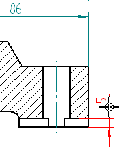
-
Press Escape.
-
-
Create a reference between dimensions in two different views.
-
Click an arrow or extension line on the notch depth dimension, as shown below. Do not click the dimension value.
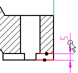
-
On the command bar, in the Tolerance group, click the Dimension Type button.

-
From the Dimension Type list, select (X) Reference.
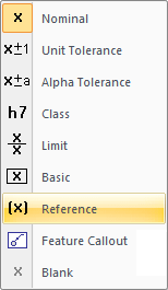
The dimension updates automatically to show the reference symbol ( ). This dimension references a dimension in the Detail view.
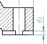
-
-
Place a dimension between centerlines:
-
Choose the Distance Between command
 .
. -
Select the center line of one hole, and then select the center line of the other hole.
-
Position the cursor above the part, and click to place the dimension.
As moving the cursor, observe the dashed line that appears between this dimension and the previously placed dimension. The dashed line indicates that the mouse button can be released and the dimension text 48 will snap into alignment with dimension text 86.
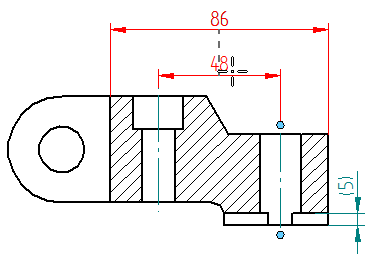
-
Press Escape.
-
-
Click the Fit button
 .
.
Add a dimension that references a dimension in another view.
When done, the dimensioned section view should match the illustration at the top of the page.
Changing dimension type and orientation
Change dimension type and orientation using the options on the Tolerance group on the Dimension command bar.
-
Dimension types control how the dimension displays, including related tolerances. Set the dimension type before or after placing a dimension.

-
Change the orientation of dimensions placed with the Distance Between command and the Coordinate Dimension commands.

-
The By 2 Points option places dimensions parallel or perpendicular to a theoretical line between the two points being dimensioning.
-
The Horizontal/Vertical option places dimensions parallel or perpendicular to the horizontal edge of the drawing sheet.
-
The Use Dimension Axis option places dimensions with respect to the element that first specified using the Dimension Axis button. Use this option when default horizontal and vertical axes are not appropriate for the geometry being dimensioning.
-
For examples of how to use these orientation options, see the Dimension command bar help topic.
Save the file
-
On the Quick Access toolbar, choose the Save command.

© 2021 UDS