Activity: Detail the top view
Detail the top view
In this activity, detail the top view. Place:
-
dimensions
-
dimension tolerances
-
dimension prefixes
-
callouts
-
feature control frames
-
datum frames
Launch the Activity: Detail the top view.
Zoom in on the top view
-
Click the Zoom Area button
 .
. -
Click above and to the left of the Top view, then drag the cursor below and to the right of the view, and click again.
-
Right-click to exit the command.
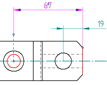
Adjust the position of retrieved dimensions in the top view
![]()
-
Delete linear dimension 19 located at the right side of the part.
-
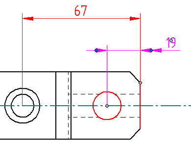
At the top of the part, position the cursor on the remaining dimension 19, so that the locate cursor is displayed.

-
Click+drag one of the dimension terminators outside the extension lines.
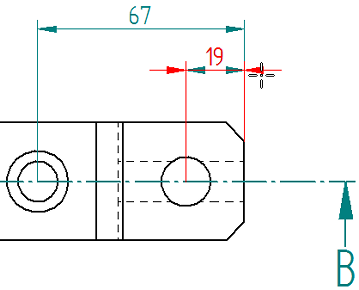
Observe that both arrows updated.
-
Click in free space to deselect the dimension.
-
Adjust the position of the text of linear dimension 19. Place the cursor on the text, and when the cursor changes to the locate cursor
 , drag the text to the right, outside the projection lines, as shown below.
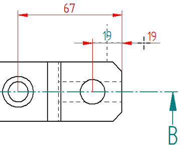 Tip:
Tip:The light blue dimension edit handle at the center of the dimension text can also been used to move the text. This technique is explained on the next page of instructions.
-
Continue to the next page to learn how to use edit handles to edit and format selected parts of a dimension.
In the Top view, adjust the positions of the retrieved dimensions to make room for new dimensions and annotations. Use the illustration above as a guide.
Use edit handles to edit dimensions
-
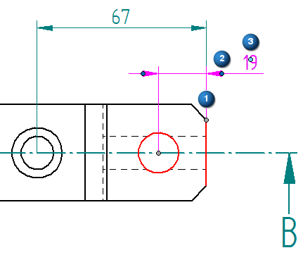
Click linear dimension 19 to display its edit handles.
The edit handles for a dimension (ISO standard) are shown below:
(1) Gray connection handles.
(2) Dark blue terminator handles.
(3) Light blue edit handles.
-
Change the dimension terminator type by doing the following:
-
Click the dark blue terminator handle to display the dimension formatting menu.
-
From the dimension formatting menu displayed at the cursor, choose Terminator Type→Double Arrow (Filled).
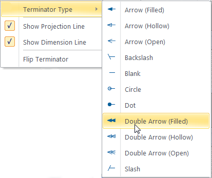
The selected terminator updates to show the double arrow filled terminator type. The other terminator is not affected.
-
Change the terminator back to the Arrow (Filled) type.
-
-
Flip the dimension terminators using a command instead of click+drag:
-
Click the dark blue terminator handle to display the dimension formatting menu.
-
Select the Flip Terminator command.
Observe that both terminators are flipped.

-
Select the Flip Terminator command again to flip the terminators back to the outside of the projection lines.
-
-
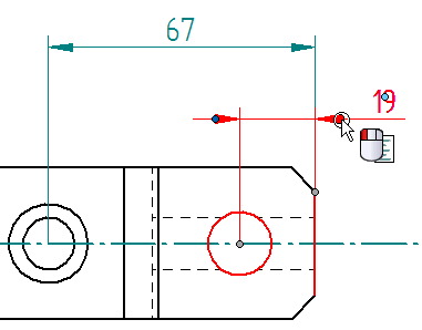
Change the length of a selected projection line:
-
Click linear dimension 67 to display its edit handles.
-
Position the cursor on one of the dark gray connection handles. When the
 cursor is displayed (1), click+drag the handle away from the connection point (2).
 The dashed lines that appear indicate that the dimension is still associated with the geometry at the gray connection point.
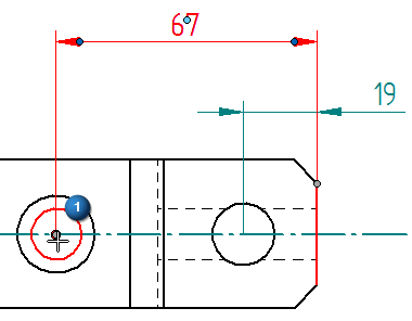

Also notice the light blue edit handle that is now visible. For ISO dimensions, this light blue projection line edit handle is coincident with the gray connection handle. It is not visible until it gets dragged.
-
Drag the light blue projection line edit handle back onto the connection handle at the center of the hole.
Note:On ANSI dimensions, the projection line edit handles are visible at all times.
ANSI dimensions also have light blue dimension line edit handles. Drag these handles to lengthen or shorten the selected end of the dimension line. Refer to the illustration below.
-
-
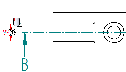
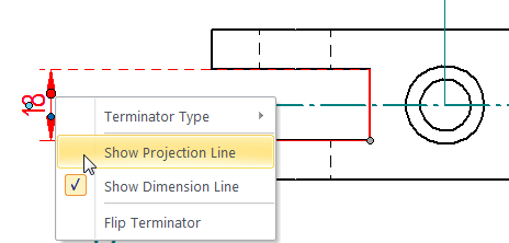
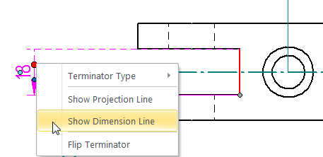
Display a half dimension:
-
Click linear dimension 18 to display its edit handles.
-
Click a dark blue terminator handle to display the dimension formatting menu.
-
Clear the Show Projection Line check mark.
-
Click the terminator handle to display the menu again, and this time clear the Show Dimension Line check mark.
-
Click in free space to update the dimension on the drawing.
-
-
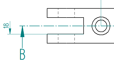
Use the terminator handle and the dimension formatting menu to show the full dimension again.
Even though the terminator is hidden, clicking in its approximate location displays the formatting menu.
Previously, it was shown how to reposition dimensions by dragging the dimension when the locate cursor is displayed. Now use edit handles to make changes to individual parts of a dimension. (Similar edit handles are available for the annotations added to the drawing, such as callouts, and feature control frames, and datum frames.)
There are three types of handles that appear on a dimension. The handle colors identify the type of edit the handle performs. The location of the handle indicates what will change.
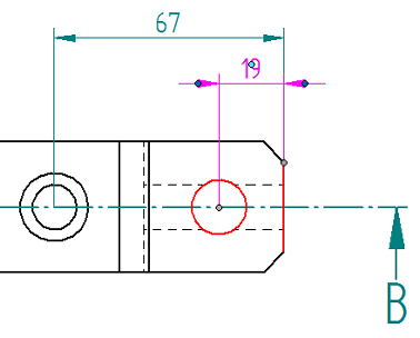
Place dimensions on the top view
![]()
-
Create a stacked dimension by doing the following:
-
Choose the Distance Between command.

-
On the command bar, set the Orientation to Horizontal/Vertical.
-
Select the top line of the part (1), as shown below.
-
Place the cursor on the circle that represents the simple hole, so that it highlights.
-
Move the cursor to the middle of the circle, and when the center point indicator appears (2), click to select it.
-
Position the dimension as shown in the illustration below, and then click.
-
The Dimension Between command is still active. Select the line at the bottom of the part, and then click to place the second dimension in the stack, as shown below.
Stacked dimensions are related. Adjust the length of all of the projections lines in a stack by dragging one of the dimensions.
-
-
Place a chamfer dimension, adding a dimension prefix that references both chamfers.
-
Choose Home tab→Dimension group→Chamfer Dimension
 .
. -
Select the vertical line at the right side of the part (1), between the chamfered lines, as shown below.
-
Select the bottom chamfer (2).
-
-
On the command bar, in the Tolerance group, click Dimension Prefix.
-
In the Dimension Prefix dialog box, in the Prefix box, type 2X, click Apply, and then click OK to close the dialog box.
-
Move the cursor to position the dimension as shown below, and then click to place it.
-
Press Escape.
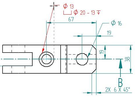
Add the missing dimensions to the Top view using the Distance Between and Chamfer Dimension commands. The view should match the illustration above when done.
The dimension prefix defined in the Dimension Prefix dialog box will be applied to each subsequent dimension added. To control whether dimension text is placed with a dimension or not, reopen the dialog box and clear the prefix, or use the Enable Prefix button in the Tolerance group on the command bar.
![]()
When the Enable Prefix button is selected, dimension text is added; when the button is cleared, dimension text is ignored.
Extract simple and counterbore hole information
![]()
-
Choose Sketching tab→Annotation group→Callout
 .
. -
In the Callout Properties dialog box, on the General page, click the Feature Callout button
 , and then click OK to continue.
The Feature Callout option causes the callout to reference the predefined property text strings on the Feature Callout page of the dialog box. The hole selected when placing the callout determines which string is used to extract information.
-
On the command bar, select Leader and Break Line.

-
Place the hole callout on the simple hole:
-
Move the cursor to the circle representing the simple hole, and when it highlights, click.
-
Move the cursor above and to the right of the part, and then click to place the callout.
-
-
On the command bar, click the Properties button
 .
. -
In the Callout Properties dialog box, customize the information to be extracted for the counterbore hole. Substitute symbols for the text 'C'BORE' and 'DEEP' on the drawing.
-
Click the Feature Callout tab.
-
Click in the Counterbore box, select the text C'BORE, and then click the Counterbore button.
-
With the cursor in the Counterbore box, press the right arrow key until the text DEEP is seen, and then double-click to select it.
-
Click the Depth button
 .
. -
This string replaces the text C'BORE with the counterbore symbol:
-
This string replaces the text DEEP with the depth symbol:
The property text strings seen in the following illustrations should match:
-
-
Click OK to close the dialog box and continue.
-
Place the callout on the counterbore hole:
-
Select the outer circle representing the counterbore hole.
-
Move the cursor above the part, and watch the annotation flip based on the cursor position. Move it slightly to the right of the hole, so the annotation is oriented as shown below, and click to place it.
-
Press Escape to end the Callout command.
-
Now adjust the position of the annotation. Click the leader line of the annotation to display its edit handles, and then begin dragging the light blue leader line edit handle to the left to reposition the callout.
Observe the dashed leader snap lines that are displayed for orienting the annotation. Release the mouse button when the leader is near the 135 degree orientation angle.
-
Click in space to finish.
The hole callout should be positioned approximately as shown in the drawing view at the top of this page.
-
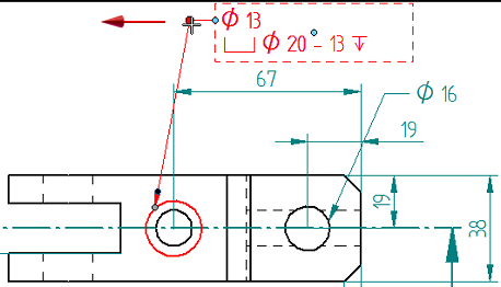
Use the Callout command with the Feature Callout option to extract hole diameter and other information for the simple and counterbore holes. The information shown in the hole callout annotation can be customized.
If needed, drag the Top view to make room for the annotations.
The hole annotations in the Top view should match the illustration above when done.
Finish annotating the top view
![]()
-
Add datum frame B to the Top view.
-
Choose Sketching tab→Annotation group→Datum Frame
 .
. -
On the command bar, do the following:
-
Clear the Leader and Break Line options.
-
In the Text box, type B.

-
-
Place datum frame B, as shown below.
-
In the Text box, type C.
-
Place datum frame C, as shown below. Use QuickPick if needed to select the line corresponding to the part edge, not the dimension extension line.
-
Press Escape.
-
-
Add a feature control frame to the simple hole and the counterbore hole.
-
Choose the Feature Control Frame command
 .
. -
In the Feature Control Frame Properties dialog box, create the frame shown below. To do this, use all of the techniques learned when annotating the Front view.
If the previous feature control frame text is displayed in the Content box, either select it and delete it, or edit it. The Preview pane updates as changes are made.
The feature control frame should look like this when finished:
-
Use the buttons to insert symbols and dividers.
-
Type the value.
-
For each datum letter A, B, and C, open the Select Reference Text dialog box to select and insert the reference value.
-
-
On the command bar, clear the Leader option.
-
Place the annotation using the simple hole callout by doing the following:
-
Click the hole callout to activate it.
-
Position the feature control frame below or above the callout, and then click to place it.

-
-
Use the same technique to place the feature control frame using the counterbore hole callout. If needed, adjust the position of dimensions and annotations to make room for it.
-
Press Escape.
-
-
Click Fit
 .
.
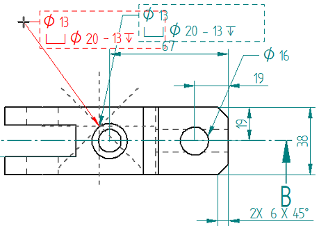
Use the Feature Control Frame command and the Datum Frame command to finish annotating the Top view. It should look like the illustration above when done.
Save and finish
-
Click the Save button
 to save the work.
 -
To exit QY CAD, on the Application menu, choose Exit QY CAD.
-
(Optional) For additional practice, add dimensions to the isometric view using the Smart Dimension command.
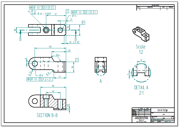
The fully detailed drawing should look like the one above.
© 2021 UDS