Place an angular coordinate dimension
-
Choose the Angular Coordinate Dimension command
 .
. -
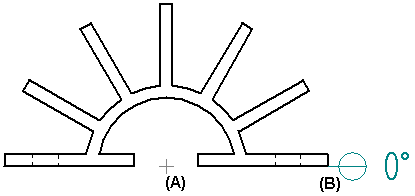
Click an element that you want to be the group center element (A).
-
Click to place the common origin (B).
-
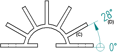
Click an element that you want to measure (C).
-
Click to place the dimension (D).
Angular coordinate dimensions should be applied to fully constrained profiles. If an angular coordinate dimension behaves unpredictably (conflict between the displayed dimension and the command bar, for example), make sure the profile is fully constrained.
-
To use a different origin element for additional dimensions, right-click to start over.
-
You can control the direction in which the angular coordinate dimension is measured with the Counterclockwise button
 on the Dimension command bar.
 -
You can add jogs when placing angular coordinate dimensions when the Enable automatic jogging option is selected on the Lines and Coordinate tab of the Dimension Style or Dimension Properties dialog box.
-
You can remove all of the jogs on an existing angular coordinate dimension by first selecting the dimension, and then clearing the Jog button
 on the command bar.
| Place coordinate dimensions between drawing views |
© 2021 UDS