Using the Angle command
The following procedures describe how to use the Angle command (Home tab→Assemble group→Angle) to apply an angular relationship between faces, edges, or planes of a placement part to the faces, edges, or planes of a part in the assembly. The Angle command is used to form an angular relationship that constrains a part to a fixed angular value, or that allows a defined angular movement by defining minimum and maximum values (for more information, see About the Angle relationship).
Insert a new part
-
To place a new part into the assembly, drag a placement part from the Parts Library into the assembly workspace.
The system automatically opens the Assemble command and the associated Assemble command bar, and highlights the placement part (for more information, see Assemble parts (workflow)).
-
On the Assemble command bar, select the Angle option from the Relationship Types drop-down list
 .
.For more information, see Using the Angle features on the command bar.
-
On the highlighted part being placed, select the face, edge, or plane element to use to form the connection.
This action identifies the measured to feature.
-
Select the assembly part that is to be used to form the relationship.
-
On the part in the assembly, select the face, edge, plane, or point element to use to form the Angle relationship.
This action identifies the measured from feature.
-
Click a plane to use to display the angle.
-
Select the Angle Type.
-
Select a single Fixed value or two values that specify a Range.
-
Fixed—To constrain the part to a specified value, select the Fixed option and then enter the value.
-
Range—To allow angular movement of the placed part, select the Range option and enter the two values (minimum angle and maximum angle) that represent the amount of angular movement that is to be allowed.
-
-
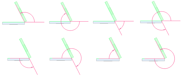
An angle can be displayed in eight possible ways. Use the Angle format to select the way the angle is to be displayed.
-
Click OK.
The Assemble command bar remains open to apply the next relationship.
-
To apply another relationship, continue with Create additional relationships.
-
To close the Assemble command and the Assemble command bar, press the Esc key.
Create additional relationships
-
To create an Angle relationship between two parts, you can do either of the following:
-
To create a relationship using the Assemble command bar, the Assemble command bar must be open. If not open, select the Assemble command (Home tab→Assemble group→Assemble). On the Assemble command bar, select the Angle icon from the Relationship Types drop-down list.
-
To create a relationship using the Angle command bar, the Angle command bar must be open. If not open, select the Angle command (Home tab→Assemble group→Angle)
.
The actions that can be performed are the same for each option. However, after the Angle command bar is opened, only an Angle relationship can be applied. The relationship type cannot be changed (see Using the Angle features on the command bar).
-
-
Select the relationship parts and features as described previously.
-
To complete the action, press OK.
-
To close the command and the command bar, press the Esc key.
© 2021 UDS