Property text codes
You can add symbols and reference data to annotation text, dimension text, drawing views, and tables. There are many ways and places to do this. For example, when a dialog box such as the Callout dialog box or the Dimension Prefix dialog box provides buttons to do so, you can click the buttons to insert symbols. When the dialog box does not provide a button interface to insert a symbol directly, you can type a three-character property text code instead.
For most types of annotations, such as text boxes, feature control frames, weld symbols, and hole tables, as well as dimension text and drawing view captions, you can use the Select Symbols and Values dialog box or the Select Reference Text dialog box to select and insert the appropriate property text codes for the symbols that you want to display and the reference data that you want to extract.
For property text that resolves to a single value, you can apply formatting to the value using the Format Values dialog box.
The following tables are organized by category:
The three-character code in the left-most column displays the corresponding symbol shown in the right-most column, or it fetches the matching value from the model. The codes must be typed exactly as listed.
Values
| Feature references | ||
| Code | Represents | Fetches this feature data |
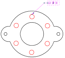
| %HC | Feature Callout | For example, displays hole diameter and depth symbols plus extracted values: |
| %HS | Size | <Size Value> For geometry selection, this is the diameter of the selected circle or arc. For a simple hole feature,this is the diameter of the hole. For a threaded hole, this is the drill diameter. |
| %DT | Diameter/Thread Size (Hole Feature) | <Size Value> (hole feature) For geometry selection, this returns the same value as Hole Size (%HS) above. For a simple hole feature, this is the diameter of the hole. For a threaded hole feature, this is the size of the thread (for example, M10). |
| %HD | Depth | <Depth Value> |
| %F1 | Hole Callout 1 | <Feature Callout 1 definition on the Callout page of the Hole Table Properties dialog box> |
| %F2 | Hole Callout 2 | <Feature Callout 2 definition on the Callout page of the Hole Table Properties dialog box> |
| %F3 | Hole Callout 3 | <Feature Callout 3 definition on the Callout page of the Hole Table Properties dialog box> |
| %F4 | Hole Callout 4 | <Feature Callout 4 definition on the Callout page of the Hole Table Properties dialog box> |
| %BS | Counterbore Size | <Counterbore Size Value> |
| %BD | Counterbore Depth | <Counterbore Depth Value> |
| %SS | Countersink Size | <Countersink Size Value> |
| %SA | Countersink Angle | <Countersink Angle Value> |
| %TS | Thread Size | <Thread Size Value> |
| %TD | Thread Depth | <Thread Depth Value> |
| %TP | Thread Pitch | <Thread Pitch Value> |
| %ZH | Smart Depth | <Smart Hole Value> |
| %ZT | Smart Thread Depth | <Smart Thread Depth Value> |
| %PH | Path Length | <Slot Path Length>, which is the sum of the lengths in the sketch. |
| %SH | Overall Length | <Overall Slot Length>, which is the path length for flat-end slots, plus the slot width for arc-end slots. |
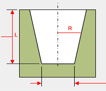
| %T1 | Taper Ratio (R:L) | <Tapered holes>, taper ratio R:L (where 1:X)
|
| %TA | Taper Angle | <Tapered hole>, taper angle |
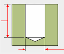
| %V1 | V-Bottom Angle | <Any hole>, V-bottom angle option
|
| %DD | Tap Drill Diameter | <Threaded hole>, the tap drill diameter. |
| %MD | Internal Minor Diameter | <Threaded hole>, the internal minor diameter. |
| %ND | Nominal Diameter | <Threaded hole>, the nominal diameter. |
| %QN | Smart Quantity | References the Hole Quantity Note information on the Smart Depth tab for hole callouts and feature callouts. You also can enter %QN directly in a dimension prefix. Example: The default Hole Quantity Note is %QC X.
|
| %QC | Quantity - Coplanar | Counts the equivalent holes on the same plane and with axes that are parallel and pointed in the same direction. |
| %QP | Quantity - Parallel | Counts equivalent holes sharing the same orientation. |
| %QA | Quantity - All | Counts equivalent holes in the part, based solely on hole parameters specified in the Hole Options dialog box. |
| Bend references | ||
| Code | Represents | Fetches this bend data |
| %BA | Bend Angle | <Bend Outside Angle Value> |
| %BN | Bend Angle Unsigned | <Bend Angle Unsigned Value> |
| %IA | Included Angle | <Bend Inside Angle Value> |
| %BR | Bend Radius | <Bend Radius Value> |
| %BO | Bend Direction | <Bend Direction Value> |
| %BI | Bend Sequence | <Bend Sequence Number> |
| %BQ | Bend Quantity | <Number of Bends> |
| Drawing view references | ||
| Code | Represents | Fetches this drawing view information |
| %VA | View Annotation Name | <View Annotation Name> |
| %LN | Annotation Sheet Number | <View Annotation Sheet Number> |
| %VS | View Scale | <Drawing View Scale Value> |
| %VR | Angle of Rotation | <Drawing View Rotation Angle> |
| %VN | Drawing View Sheet Number | <Drawing View Sheet Number> |
| %AS | Suffix | <Drawing View Caption Suffix> Suffix (%AS) is only evaluated on the Caption tab (Drawing View Properties dialog box). |
| Weld bead references | ||
| Code | Represents | Fetches this weld bead data |
| %TT | Target Thickness | <Weld Bead Target Thickness Value> |
| %GL | Gap Length | <Weld Bead Gap Length Value> |
| %BL | Bead Length | <Weld Bead Length Value> |
| %NB | Number of Beads | <Number of Weld Beads> |
| %PI | Pitch | <Weld Bead Pitch Value> |
The following property text codes are valid only for Fit dimensions in a tolerance table.
| Fit dimension references in tolerance tables | |
| Code | Displays |
| %{Dimension Value} | Value |
| %{Dimension Class Fit} | Class |
| %{Class Fit Upper Stack Tolerance} | Upper Stack Tolerance |
| %{Class Fit Lower Stack Tolerance} | Lower Stack Tolerance |
| %{Class Fit Upper Limit Tolerance} | Upper Limit Tolerance |
| %{Class Fit Lower Limit Tolerance} | Lower Limit Tolerance |
| %{Class Fit Upper Stack Tolerance}%RT%{Class Fit Lower Stack Tolerance} | Upper and Lower Stack Tolerance |
| %{Class Fit Upper Limit Tolerance}%RT%{Class Fit Lower Limit Tolerance} | Upper and Lower Limit Tolerance |
%RT in the tolerance table code for combined upper and lower tolerances ensures they are formatted one above the other in a single table cell.
| Block diagram references | ||
| Code | Represents | Fetches this block data |
| %{Block Name|GBLM} | Block name | The master block name, such as BATTERY. |
| %{Block Property|GBLK} | Block property name-value pairs defined in the Block Properties dialog box. | For the block property BATTERY TERMINAL, fetches the value POSITIVE or NEGATIVE. |
| %{Block Label|GBLL}, | Block label name-value pairs defined in the Block Label Properties dialog box. | Label 1 Inventory Number Notes |
| %{Block View Name|GBLM} | Block view name | The name of the alternate block view, such as VIEW 1. |
The block property text codes are available from the Select Property Text dialog box when the property source is From graphic connection to block.
Symbols
The following property text codes are valid for the QY CAD ANSI Symbol, Solid Edge ISO Symbol, and QY CAD GDT Symbol fonts.
| Geometric characteristic symbols | ||
| Code | Represents | Displays this symbol |
| %FL | Flatness |
|
| %SR | Straightness |
|
| %CI | Circularity |
|
| %CY | Cylindricity |
|
| %PP | Perpendicularity |
|
| %AN | Angularity |
|
| %PR | Parallelism |
|
| %PS | Profile of a Surface |
|
| %PL | Profile of a Line |
|
| %CR | Circular Runout |
|
| %TR | Total Runout |
|
| %PO | Position |
|
| %CO | Concentricity |
|
| %SY | Symmetry |
|
| %CX | Coaxiality |
|
| %AP | Tolerance of axial section profile |
|
| %AX | Axis intersection tolerance |
|
| %OC | Orientation Constraint |
|
| Material condition symbols | ||
| Code | Represents | Displays this symbol |
| %MC | Maximum |
|
| %LC | Least |
|
| %SC | Regardless of Feature Size |
|
| %RC | Reciprocity Condition |
|
| Tolerance zone symbols | ||
| Code | Represents | Displays this symbol |
| %PZ | Projected |
|
| %TZ | Tangent Plane |
|
| %FZ | Free State |
|
| %ER | Envelope Requirement |
|
| %UD | Profile Unequally Disposed |
|
| %IN | Independency |
|
| %TL | Translation |
|
| %MN | Minimax |
|
| %LT | Least Squares |
|
| %MM | Minimum Circumscribed |
|
| %MI | Maximum Inscribed |
|
| %DV | Derived |
|
| Dimensioning symbols | ||
| Code | Represents | Displays this symbol |
| %DI | Diameter |
|
| %DG | Degree |
|
| %BT | Between |
|
| %ST | Statistical Tolerance |
|
| %CF | Continuous Feature |
|
| %SQ | Square |
|
| %CB | Counterbore |
|
| %SF | Spotface |
|
| %CS | Countersink |
|
| %DP | Depth |
|
| %IL | Initial Length |
|
| %AL | Arc Length |
|
| %PM | Plus Minus |
|
| %AN | Taper Angle |
|
| %A2 | Taper Angle 2 |
|
| %A3 | Taper Angle 3 |
|
| %A4 | Taper Angle 4 |
|
| %SG | Symmetric Taper Angle |
|
| %S2 | Symmetric Taper Angle 2 |
|
| %Gd Note: The second letter is lowercase. | Material Thickness |
|
| %TW | Two-point Size |
|
| %LS | Local Size |
|
| %GG | Least-squares Association |
|
| %GX | Maximum Inscribed Association |
|
| %GN | Minimum Circumscribed Association |
|
| %GC | Minimax Association |
|
| %CC | Calculated Circumference Diameter |
|
| %AD | Calculated Area Diameter |
|
| %VD | Calculated Volume Diameter |
|
| %SX | Maximum Size |
|
| %MS | Minimum Size |
|
| %AS | Average Size |
|
| %SM | Median Size |
|
| %SD | Mid-range Size |
|
| %RS | Range of Sizes |
|
| %DS | Standard Deviation of Sizes |
|
| GOST weld symbols | ||
| Code | Represents | Displays this symbol |
| %FW | Fillet Weld |
|
| %HW | Heat |
|
| %HB | Heat Back |
|
| %SW | Smooth |
|
| %SB | Smooth Back |
|
| %SN | Stagger Chain |
|
| %SK | Stagger Check |
|
| %UL | Not All Around |
|
| %NU | Number |
|
| %DA | Diameter |
|
| %PN | Plus Minus |
|
| %DR | Degree |
|
| Other symbols | ||
| Code | Represents | Displays this symbol |
| %CL | Centerline |
|
| %PT | Parting Line |
|
| %OV | Oval |
|
| %RL | Rectangle |
|
| %RA | Rotated View (ESKD standard) |
|
| %CA | Rotated View Counterclockwise (GB standard) |
|
| %C2 | Rotated View Clockwise (GB standard) |
|
| %GE | Greater than or equal to |
|
| %LE | Less than or equal to |
|
| %RT | Carriage Return | Inserts a new line. |
© 2021 UDS


