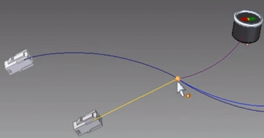
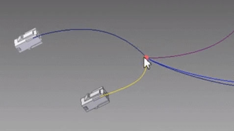
Working with QY CAD Wiring and Harness Design
QY CAD Wiring and Harness Design consists of QY CAD Wiring Design and Solid Edge Harness Design
QY CAD Wiring Design is useful when creating wiring diagrams that outline the wiring connections between components. These diagrams also help validate the design by using electrical simulations, such as short circuits, voltage drops, and wiring size errors.
QY CAD Wiring Design features and benefits include:
-
Rapid circuit design.
-
Electrical design and validation.
-
Automatic cross-referencing for multi-sheet parts and wires.
-
Customizable drawing styles.
-
Automated report generation.
-
Built-in libraries for such things as components and symbols.
-
Electrical simulations for short circuits, voltage drops, and wire sizing errors.
-
Close integration with QY CAD Harness Design for wiring data exchange.
QY CAD Harness Design is useful when creating a graphical layout of the wires within the harness.
QY CAD Harness Design features and benefits include:
-
Rapid graphical layout and engineering of harness and form board designs.
-
Automatic part selection of terminals, seals, and connectors.
-
Automatic harness report generation, including BOMs and cutting lists.
-
Wire length calculations, which include terminal and connector add-on or knock-off values.
-
Automated generation of connector, wire, and splice tables.
For more information on QY CAD Wiring and Harness Design, see the help delivered with the QY CAD Wiring and Harness Design application.
Configuring network properties for QY CAD and QY CAD Wiring and Harness Design
Before exchanging data between QY CAD and QY CAD Wiring and Harness Design, you must configure the network properties for both products. These properties specify the location of QY CAD Wiring and Harness Design, which can reside on the same machine as QY CAD or on a remote machine.
To configure network properties:
Initializing connected mode
After configuring the network properties for QY CAD and QY CAD Wiring and Harness Design, you are ready to enter connected mode, which provides file-less data exchange between QY CAD and QY CAD Wiring and Harness Design, and helps keep the data in sync.
To connect QY CAD with QY CAD Wiring and Harness Design:
-
In Electrical Routing, click the Home→Electrical→Connect
 button.
 -
In QY CAD Wiring and Harness Design, click the Workflow→QY CAD Connect
 button.
While in connected mode, the Connected Mode Log Viewer pane displays actions and information about the transactions between QY CAD and QY CAD Wiring and Harness Design. To clear the log pane, right-click in the pane and then click Clear. The log files are stored in the <user>/AppData/Local/Temp folder.
In connected mode, you do such things as:
Exchanging harness topology information between QY CAD and QY CAD Wiring and Harness Design
You can export electrical harness topology data from QY CAD to HX2ML format and then import the data into QY CAD Wiring and Harness Design in either connected or disconnected mode. This enables ECAD customers to easily exchange data between QY CAD Wiring and Harness Design and QY CAD Electrical Routing.
Several optional properties can be exported from QY CAD for bundles, connectors, nonelectrical components, and splices. These include properties such as, Bend radius, Diameter, Name, Part number, Start and End points, and Length.
In addition to these optional properties, there are three mandatory properties that you must define in QY CAD to ensure successful import into QY CAD Electrical:
-
Connector Type
-
Device Type
-
Fixing Type
Once you specify the harness related properties in QY CAD and the HX2ML information is imported into QY CAD Harness Design, the harness drawing is automatically generated.
Preparing for harness topology exchange
Before exchanging the harness topology information, you should prepare the harness in QY CAD by doing the following:
- Route wires and cables through bundles
-
Route all wires and cables through bundles because information for components that are connected to wires and cables not included in a bundle is not included in the harness exchange.
- Assign values to user defined properties needed for HX2ML
-
The HX2ML file used in the harness exchange requires some properties that are not present by default in QY CAD. These properties are created for the respective QY CAD objects by reading the se_harness_hx2ml.txt file, which should be placed in the $:\Program Files\UDS\QY CAD 2021\Preferences folder.
Note:If the file is not present in the proper location, the HX2ML file will be created with only the attributes it can retrieve.
- Specify the node reference/position of the splice on the bundle
-
In QY CAD you cannot create a splice on wires contained in a bundle without splitting the bundle. QY CAD Wiring and Harness Design does support such cases by merging the bundles which have the same shared node at the ends of the adjacent bundles. In this case, the splice position sent from QY CAD is always at the start and end positions of the adjacent bundles.
In QY CAD Wiring and Harness Design, you can merge two bundles if the following is true:
-
The diameters and maximum diameters are the same for both.
-
The bend radius is the same for both.
-
Both bundles have either unique user-defined properties or all common user properties are the same.
-
Exchanging harness topology data in connected mode
To exchange harness topology data in connected mode:
-
Once you have prepared the harness in QY CAD, open QY CAD Wiring and Harness Design.
-
In QY CAD Wiring and Harness Design, click the Workflow→Configure button
 .
. -
On the Connection Properties dialog box, enter the appropriate Port name for the Remote Application and Local Application.
-
In QY CAD Electrical Routing, click the Home→Electrical→Connect
 button.
A log viewer displays actions and information about the transactions between Solid Edge and QY CAD Wiring and Harness Design.
-
In QY CAD Wiring and Harness Design, click the Workflow→QY CAD Connect
 button.
 -
In QY CAD Wiring and Harness Design, click Workflow → Bridge In to display the 2D representation of harness topology created in QY CAD.
Exchanging harness topology data in disconnected mode
To exchange harness topology data in disconnected mode:
-
In QY CAD, once you have prepared the harness, on the Application menu, point to Save As, then choose Save As ECAD.
-
On the Save As ECAD dialog box, set the Document field to UDS - QY CAD Electrical - Harness Topology and click OK.
-
On the Save as - Harness topology dialog box, specify a name and location for the xml file and click Save.
You are now ready to import the harness information into QY CAD Wiring and Harness Design.
-
In QY CAD Wiring and Harness Design, click Workflow → Bridge In.
-
On the File Open dialog box, use the Browse button to locate and select the .xml file and then click Open.
The .xml file is imported and the harness preview displays the 2D representation of the harness design.
-
Click Process to create the harness drawing.
Adding splices during data exchange
If you import data from QY CAD Wiring and Harness Design that contain splices, the splices are automatically created in QY CAD Harness Design.
Splices are created at the midpoint between the first two available components to which it connects to the wires.

Once the splice position is known, the other wires that connect to it are routed to the splice. Afterward, you can move the splice to the appropriate position.

Once placed, you can edit the splice to make any needed changes. You can also use the Assign Terminals dialog box to change the terminal name.
Splices are considered to be components and they also support terminals. Because splices are considered to be components, splice attributes specify information about the splices in the cmp file. To differentiate splices from other components, set the Component type attribute to 1. Other splice attributes include Splice terminals, Splice diameter, and Splice Material. Wires are now specified by splice terminal instead of splice name in the .con file.
When imported, the splice entry is shown in blue in the harness wizard. You can use the harness wizard to apply the other attributes to the splice.
© 2021 UDS