Variable Table Motor command

You can use the Variable Table Motor command (Home tab→Motors group→Variable Table Motor) to simulate motion in an assembly by incrementing the variable associated with an angular or linear assembly relationship by a specified amount over a period of time. This allows for more complex motions than can be achieved using the Linear Motor command or the Rotational Motor command (for more information, see the Rotational and Linear Motor commands).
The Variable Table Motor can be used to:
-
Animate patterns
-
Animate variable table formulas and equations
-
Aid in animating adjustable assemblies
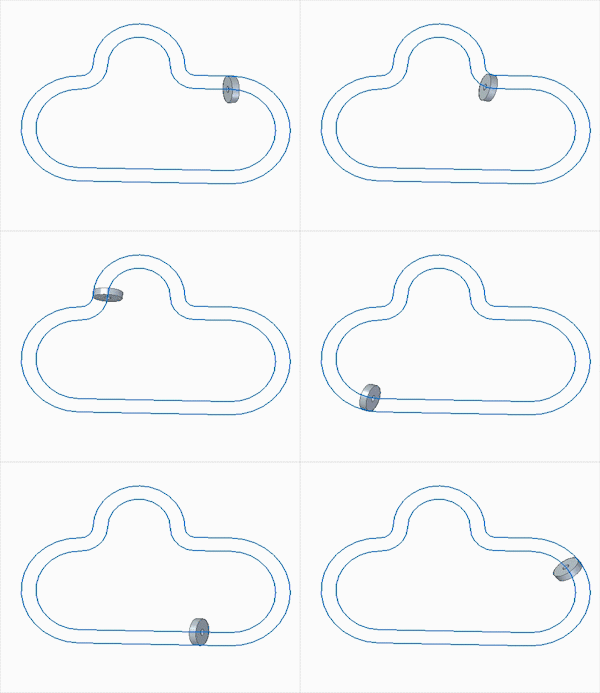
For example, the follower in a path relationship can be moved along the path by incrementing a fixed Path relationship variable value in the Variable Table (Tools tab→Variables group→Variables) at a specified speed. The following animation depicts how a follower is moved along a edge chain path using a Variable Table Motor. 
You can use this capability to define a wide variety of movements. Valid variables can be any driving distance or angular Variable Table parameter. Driven variables are not supported.
The Variable Table Motor works with existing motors (Linear and Rotational) in the motor simulation timeline. To accomplish this, linear and rotation motors update from the current position to the next position (processed incrementally). Direction vectors and axis are defined and updated using the current position of the component.
The Variable Table Motor dialog box allows you to:
-
Identify the driving variable in the Variable Table
-
Define speed
-
Optionally limit movement
-
Control direction
If a relationship that is used to define the motion is deleted or becomes driven, the motor is shown in an error state in the Motors collector in the PathFinder. Invalid relationship variable values for a motor in an error state are not indicated in Variable Table. If the variable value is invalid in the Variable Table, the motor is shown in an error state in the Motor collector in the PathFinder.
A Family of Assemblies motor must be defined for all members. The simulation timeline only processes the active member. If the variable is excluded or suppressed from the active member, the motor performs no action.
In the simulation timeline, a Variable Table Motor behaves just like any other existing motor. It appears in the Motors collector using its PathFinder name.
Variable Table Motors have the following characteristics:
-
A Variable Table Motor definition can be reversed or mirrored in the simulation timeline.
-
If a Variable Table Motor attempts to set a variable value and it fails, no error is issued during simulation. The value just does not change.
-
More than one Variable Table Motor can be defined using the same variable in the Variable Table.
-
The simulation timeline does not allow motors of the same type on the same part to be invoked at the same time.
-
The Physical Motion and Detect Collisions options are not valid when defining a Variable Table Motor using the Motor Group Properties dialog box.
Right-click a Variable Table Motor in the Motors collector of the PathFinder to edit its definition, delete the motor, or change its name.
See the Variable Table Motor workflow for more information about the procedure used to define a Variable Table Motor and apply it to a simulation.
© 2021 UDS