Activity: Create a cutout
Create a cutout
In this activity, you will draw a rectangle that you will use to create a cutout in the sheet metal part.
Launch the Activity: Create a cutout.
Draw a rectangle
-
Choose the Home tab→Draw group→Rectangle list→Rectangle by 2 Points command
 .
. -
Position the cursor over the face, as shown, and press the F3 key to lock the plane.
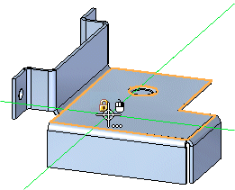
-
Click to place the first point and drag a diagonal line across the bend, approximately as shown. The line you draw represents the diagonal of the rectangle, and the system draws connected lines accordingly.
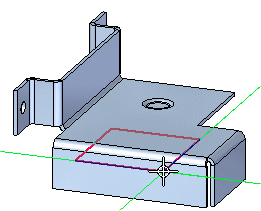
-
Click to finish the rectangle.
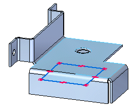
![]()
Dimension the height of the rectangle
-
Choose the Home tab→Dimension group→Smart Dimension command
 .
. -
Click the edge of the rectangle, and place the dimension as shown.

-
In the dimension edit control, type 80, then press Enter.
Dimension the width of the rectangle
-
Click the right edge of the rectangle, and place the dimension, as shown.
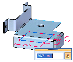
-
In the dimension edit control, type 50, then press Enter.
The Smart Dimension command should still be active.
Dimension the distances between the rectangle and the part edges
-
Choose the Home tab→Dimension group→Distance Between command
 .
. -
Click the left edge of the flange, then the left edge of the rectangle, and click to place the dimension.
-
In the dynamic edit control, type 27 and press Enter.
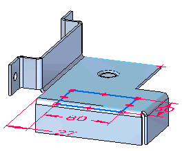
-
Right-click to restart the command.
-
Click the top edge of the rectangle, then click the highlighted part edge, and click to place the dimension as shown.
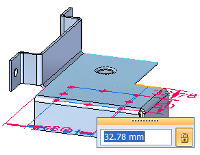
-
In the dynamic edit control, type 40 and press Enter.
![]()
Construct a cutout
![]()
In the next few steps you will use the rectangle, along with the Cut command, to construct a cutout across a bend.
-
Choose the Home tab→Sheet Metal group→Cut command.
Observe the Cut command bar

Take a few moments to observe the options on the Cut command bar:
-
 : The Face Normal Cut Types option specifies the type of cut you want to create.
 -
 : The Extents option specifies the extent type for the cut.
 -
 : The Symmetric option creates the cut symmetrically about the region.
 -
 : The Keypoint option sets the type of keypoint you can select to define a feature extent.
 -
 : The Wrapped Cut Option specifies that the affected bends are flattened during profile edit.
 -
 : The Open/Closed Profile option toggles between open and closed profile support.
 -
The Selection Type option specifies a single or chain sketch selection.
Set the Wrapped Cut option
-
Set the Wrapped Cut option
 .
.
Select a region for the cutout
-
Position the cursor over the region and click.
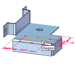
-
Hold the <Ctrl> key, position the cursor over a second region and click.
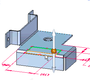
Preview the cutout
-
Right-click to preview the cutout.

Finish the cutout
![]()
-
Right-click to finish the cutout.
Save the file
![]()
This completes the tutorial.
-
On the Quick Access toolbar, click the Save button
 to save the completed part.
© 2021 UDS