Placing a part in the assembly model
Position a part in the assembly
![]()
In the next few steps, place a name plate onto the micrometer frame.
Learn how to find and select parts using Parts Library.
Learn how to position parts using assembly relationships and the Assemble command bar.
Launch the Placing a part in the assembly model activity.
Part positioning overview
![]()
To position parts in an assembly, a variety of assembly relationships are applied.
For the name plate part, apply a mate relationship and two axial align relationships to fully position the name plate with respect to the frame.
QY CAD provides a tool called FlashFit to apply each of these relationships, without having to specify the exact relationship type to use.
In the next few steps, use FlashFit to fully position the name plate as shown above.
Display the Parts Library pane
-
Choose Home tab→Components group→Insert Component command.

The Parts Library displays. It stays open as long as the Insert Component command is active.
-
Press Esc to exit the command.
-
On the left or right side of the QY CAD window, depending on the user interface theme selected, move the cursor over the Parts Library tab, but do not click.
The Parts Library tab displays.
-
Move the cursor into the graphics window, away from the Parts Library pane, and notice that the Parts Library pane closes.
As long as the cursor hovers over it, the pane will continue to display.
-
Move the cursor over the Parts Library tab, and click.
-
Move the cursor away from the Parts Library pane, and notice that the pane remains displayed.
-
Now move the cursor into the graphics window, away from the Parts Library pane, and click.
The Parts Library tab closes.
Both the PathFinder and Parts Library panes will be used to select and position parts in the assembly.
To make it easier to see the contents of the Parts Library and the PathFinder panes, maximize their size.
In the instructions that follow, work with information in the Parts Library pane. Use whichever method of displaying the pane is more comfortable.
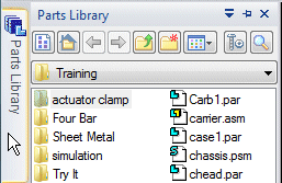
Set the Parts Library folder

-
On the Parts Library tab, click the arrow (1) on the right side of the Look In control and then browse to the QY CAD Training folder.
The default location of the QY CAD Training folder is:
C:\Program Files\UDS\QY CAD 2022\Training
However, the system administrator may have chosen a different location.
-
On the Parts Library tab, click the Views button
 , and then select the Details option.
If the working folder on the Parts Library tab is not the QY CAD Training folder, do the following:
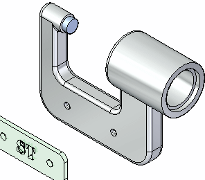
Place and position a nameplate on the part.
![]()
In the next few steps, you place and position the nameplate part as shown.
-
Press Esc to end the current command.
-
Use the Home tab→Select command to select the incorrectly placed part.

-
Press Delete on the keyboard to delete the part.
-
Back up to the step where part placement begins, and try again.
For the remainder of this tutorial, if a part is positioned incorrectly or you are confused about the steps while positioning a part, do the following:
Drag the name plate part into the window.
![]()
-
Display the Parts Library.
-
In the file list area on the Parts Library tab, drag the file NamePlate1.par into the assembly window, and then release the mouse button at the approximate position shown above.
The nameplate is placed in the assembly, as shown below.
Examine the command bar
When placing the name plate part into the assembly, the command bar displays. It is shown horizontally here, but it may display vertically, depending on the user interface theme selected. In either case, the command bar displays the same information and options.
-
Beginning at the left or top, examine the command bar, and notice the options:
 Assemble
-
The Assemble command is active using the FlashFit placement option.
 Occurrence Properties
-
Displays the Occurrence Properties dialog box. Use this dialog box to define whether the part is displayed in higher level assemblies, counted in parts lists, and so forth.
 Construction Display
-
Displays or hides elements for the part being placed, such as reference planes, sketches, and construction surfaces. This can make it easier to position certain types of parts.
 Relationship List
-
Displays the relationships used to position a part. When editing the position of a part after placement, select the relationship to redefine from the list.
 Relationship Types
-
Use the Relationship Types option to select which assembly relationship option to use for positioning a part.
 Options
-
Displays the Options dialog box. Use this dialog box to set the FlashFit options, Reduced Steps option, and so forth.
 Activate Part
-
Use the Activate Part button to select a part and activate it. When placing a subassembly using FlashFit or the Reduced Steps mode, the parts in the subassembly must be active before selecting a face. If the subassembly is not already active, use the Activate Part button to activate the placement part in the subassembly which contains the face to select.
 Offset Type
-
Use the Offset Type to define a fixed numeric offset value based on the relationship being defined.
 Offset Value
-
Use the Offset Value box to enter the fixed offset value.
 Unlock Rotation
-
With this option, use another assembly relationship to define the rotational orientation of the part. For example, apply an angle relationship.
The Lock Rotation option fixes the rotational orientation of the part. This option is useful when the rotational orientation of the part is not important, such as for a bolt being positioned in a hole.
- Flip
-
The Flip button repositions a part to the opposite side of a face, changing a mate relationship to a planar align relationship.
Review the part placement options
-
On the Assemble command bar, click the Options button.
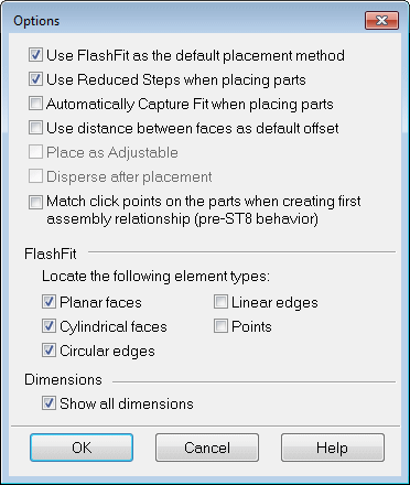
-
On the Options dialog box, ensure that the options match the illustration.
Notice that the FlashFit option specifies what types of faces FlashFit recognizes.
-
Click OK to dismiss the dialog box.
For this tutorial and most part positioning scenarios, the FlashFit settings shown work well.
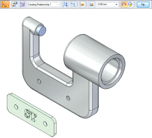
Mate the name plate to the frame
![]()
When selecting faces for the first assembly relationship, QY CAD repositions the part being placed based on the approximate positions on the faces selected on the placement part and the part in the assembly.
Use FlashFit to apply the first mate relationship.
-
On the Assemble command bar, in the Relationship Types list, ensure that the FlashFit option
 is active.
For this part, the default offset value of zero, where the parts touch, is the appropriate option.
A mate relationship positions a part by orienting two planar faces so that they face each other. Mated faces can touch or be offset from each other.
Use QuickPick to select the planar face on the name plate
![]()
-
Hover over the face shown highlighted in the top illustration, and notice that the cursor image changes to indicate that multiple selections are available. Also notice that the cursor image indicates which button to click to display the QuickPick list.

-
Right-click to display the QuickPick list.
Move the cursor over the different entries in QuickPick, and notice that different elements of the model highlight.
-
Use QuickPick to highlight the planar face shown in the bottom illustration, and then left-click to select it.
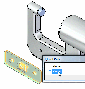
Use QuickPick to select the exact element wanted, the first time, without having to reject unwanted elements.
Select the mating face on the frame
![]()
If the QuickPick cursor displays, but the proper face highlights, bypass QuickPick by simply clicking the face.
-
Select the front face of the frame part, as shown in the illustration.
Observe the result
![]()
The mate relationship repositions the name plate in the assembly.
Because only one assembly relationship is applied, the position of the name plate might be different than the illustration.
Axially align the name plate with the frame
![]()
In the next few steps, use FlashFit to apply axial align relationships between the bolt holes on the name plate with the bolt holes on the frame.
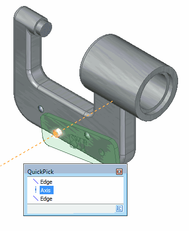
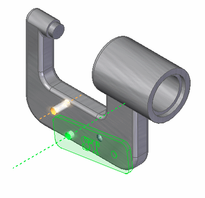
Select the cylindrical axes to align
You want to align the cylindrical axis on the name plate with the cylindrical axis on the frame.
-
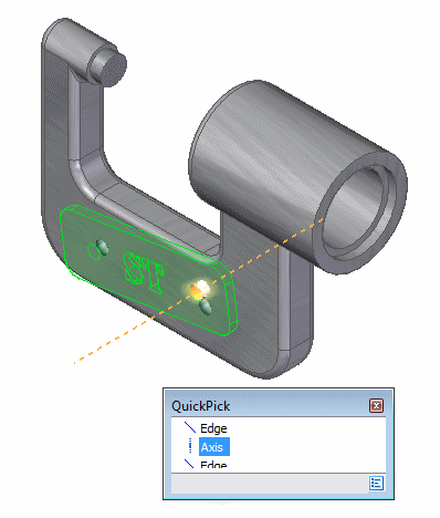
Use QuickPick to select the axis on the name plate, as shown in the illustration.
-
Select the cylindrical axis on the frame part as shown in the illustration.
Observe the result
![]()
Although the name plate appears correctly positioned on the frame, no relationship prohibits the name plate from pivoting about the cylindrical axes just aligned.
In the next steps, apply another axial align relationship to fully position the name plate.
Apply another axial align relationship
-
Select the cylindrical axis on the name plate, as shown in the illustration.
Depending on where the cursor is positioned, QuickPick may be needed to select the proper axis.
-
Select the cylindrical axis on the frame as shown in the illustration.

To prevent the name plate from rotating out of position, apply a second axial alignment relationship.
Observe the result
![]()
The name plate part is now fully positioned in the assembly.
-
Notice that the Assemble command bar is dismissed.
-
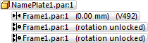
In the top pane of PathFinder, click the NamePlate.par:1 entry.
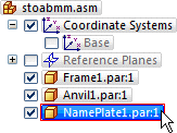
Notice that the applied relationships display in the bottom pane of PathFinder.
Use Save As to save the assembly
![]()
-
On the Application menu, click Save As→Save As.
-
On the Save As dialog box, in the File name box, save the assembly to a new name or location so that other users can complete this tutorial using the original assembly file.
-
In the Save As dialog box, click Save.
This completes the adding a part to the assembly and positioning it with relationships portion of the tutorial.
© 2021 UDS