Activity: Move parts within the context of the assembly
Move parts within the context of the assembly
This activity:
-
Sets the Faces Priority selection option
-
Examines the steering wheel
-
Examines Design Intent relationships
-
Uses the primary axis of the steering wheel to modify the part
-
Uses the secondary axis of the steering wheel to move the hole feature
Launch the Activity: Move parts within the context of the assembly.
Display the base coordinate system for the base plate
-
Display the PathFinder tab
 .
. -
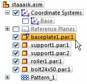
In the top pane of PathFinder, position the cursor over the baseplate1.par entry, then right-click to display the shortcut menu.
-
On the shortcut menu, click Show/Hide Component, then choose the Coordinate Systems option. Click OK. This displays the base coordinate system for the baseplate1.par.
-
In the graphics window, click in empty space to deselect the baseplate1.par.
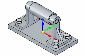
The base coordinate system for the base plate part is displayed in the graphics window, as shown.
Change the Selection Filters option and maximize the Select command bar
-
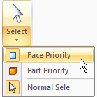
Choose the Home tab→Select→Face Priority.
The Face Priority option makes it possible to select faces before parts. This is a useful option when editing a model by moving faces with the steering wheel.
Select the face on the base plate
![]()
-
Position the cursor over the face shown, and then click to select it.
Observe the steering wheel, command bar, and Design Intent
![]()
Notice the tools that display when selecting the face:
-
The steering wheel (1) displays at the location of the face selection.
-
The Move command bar (2).
-
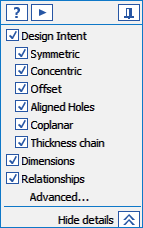
Design Intent panel as shown below.
Learn more about these tools in the next few steps.
Design Intent overview
Click the Advanced... option in the Design Intent panel to open the Advanced Design Intent panel.
Design Intent Panel

Advanced Design Intent panel
Depending on the current configuration of your computer, the active Design Intent settings on your computer may be different than the illustration.
-
On the Advanced Design Intent panel, click the Restore Defaults button
 .
.
The Design Intent settings should now match the illustration.
Use the Design Intent options to locate and show the relationships between faces in the current select set and the rest of the model. Use this information to control how synchronous modifications are performed.
The Design Intent panel opens when making the following types of synchronous modeling modifications:
-
Moving or rotating model faces.
-
Defining 3D geometric relationships between model faces using the Relate command.
-
Editing the dimensional value of a 3D PMI dimension.
The current Design Intent settings specify the following:
-
Concentric faces will remain concentric.
-
Coplanar faces will remain coplanar.
-
Tangent edges will remain tangent.
-
Model symmetry about the base coordinate system will be maintained.
For the current move operation, the Symmetric About Base option will be illustrated.
When editing parts using the steering wheel, symmetry about the base coordinate system is determined with respect to the base coordinate system in the part document where the face was selected.
Modify the model using the primary axis on the steering wheel
![]()
-
Position the cursor over the primary axis on the steering wheel and click to select it, as shown above.
-
Move the cursor to the left and right.
Notice the following as you move the cursor:
-
The adjacent faces of the model update automatically as you move the face.
-
The relationship indicators on the Advanced Design Intent panel update, with the Symmetric About Base: (Z)X option now displayed.

-
The model is modified symmetrically about the (Z)X plane of the base coordinate system.
-
The dynamic input box is displayed near the cursor so you can type a precise value for the delta distance of the move.
-
-
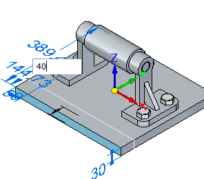
Position the cursor such that the model face is larger than its original size, then in the dynamic input box, type 40. Press Enter.
Observe the result
![]()
Notice that the width of the base plate was increased in size by a total of 80 millimeters, divided symmetrically about the (Z)X plane of the base coordinate system of the base plate part.
When editing parts using the steering wheel and Design Intent relationships, symmetry about the base coordinate system is determined with respect to the base coordinate system in the part document where the face was selected.
Prepare to select another face to move
![]()
-
Move the cursor away from the parts and the steering wheel, then double-click the left mouse button quickly to clear the select set and restart the Select command.
In the next few steps, reposition the hole feature on the right support part using the secondary axis on the steering wheel, as shown above. Because the support part was placed in the assembly twice, both supports will update.
This move operation will also illustrate how the preserved Design Intent concentric relationship ensures that faces which are concentric to the face or feature you are moving stay concentric.
The position of the roller part will update as well due to the assembly relationships applied earlier.
Select the hole feature on the support
![]()
-
Position the cursor over the face shown, then wait for the QuickPick cursor to display.
-
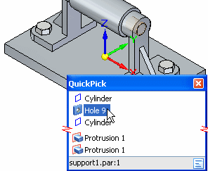
Right-click to display QuickPick, then position the cursor over the Hole 9 entry. Also notice that at the bottom of QuickPick, the occurrence name is displayed: support1.par:1, as shown below.
-
In QuickPick, click to select the hole feature on support1.par:1.
Reposition the secondary axis on the steering wheel
![]()
Notice that the steering wheel is now centered over the hole feature, as shown.
Move the hole feature
![]()
-
Position the cursor over the axis on the steering wheel, and when it highlights, click to select it, as shown above.
-
Move the cursor above the model vertically.
As before, the adjacent faces of the model update automatically, and the dynamic input box displays near the cursor so a precise value can be entered.
-
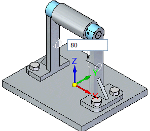
In the dynamic input box, type 80, then press Enter, as shown below.
Observe the result
![]()
The height of the support part is lengthened as shown. Notice that the outer faces on the support parts stayed concentric to the hole feature that was moved. This is because the Design Intent concentric relationship is preserved.
The position of the roller part also updates, due to the assembly relationships applied.
Save the final assembly
![]()
-
On the Quick Access toolbar, choose Save to save the completed part
 .
.
© 2021 UDS