Activity: Edit the offset value of the mate relationship
Edit the offset value of the mate relationship
This activity:
-
Edits the offset value of the mate relationship of the roller part
Launch the Activity: Edit the offset value of the mate relationship.
Open the assembly file
-
Open the assembly saved in the previous activity, if it is not already open.
Rotate the view to a top orientation
![]()
-
Hold the Ctrl key on the keyboard down, then press T to rotate the view to the top orientation.
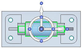
Notice the clearance mismatch between the roller and support
![]()
Notice there is no gap between the roller and support parts on the right side, but there is a gap on the left side. When applying the mate relationship, the default mate offset value was zero.
For this part, equal clearance on both sides of the roller is desired. Edit the offset value of the mate relationship to move the roller such that equal clearance is achieved.
There are commands available in QY CAD on the Inspect tab to measure the gap distance between the parts. For this tutorial, the proper value for the offset is provided.
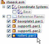
Select the roller in PathFinder

-
Position the cursor over the roller1.par entry in PathFinder, click to select it, then move the cursor away from the entry in PathFinder.
Notice the following:
-
The relationships used to position the part display in the bottom pane of PathFinder, as shown.

-
The part color changes to the Select color in the graphics window.

Select the mate relationship

-
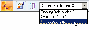
To change the offset for the mate relation on the part, click the Edit Definition command.

Notice that the Assemble command bar displays. Edit the offset value for the mate relationship by selecting it from the Assemble command bar.

Edit the offset value for the mate relationship
![]()
-
On the Assemble command bar, in the Offset Value box, type 2, then press Enter.

-
On the Home tab, click the Select tool, and then click in the graphic window to deselect the roller part.
In the graphics window, notice that the roller part is repositioned such that there is now equal clearance on both sides, as shown above.
Changing the offset to 2.00 mm creates a fixed offset for the mate relationship. Another relationship that will center the roller between the two supports is the center-plane relationship. The center-plane relationship calculates the offset by the position of the faces and if the distance between the support changes, the roller is still centered between them. The center-plane relationship is more practical in this scenario; however, it is important to understand offset distances with the mate relationship.
Rotate the view
![]()
-
On the keyboard, hold the Ctrl key down, then press I to rotate the view to the isometric orientation.
Save the assembly
![]()
-
On the Quick Access toolbar, choose Save
 .
.
In the next activity, place a bolt into one of the holes on the support part, and then pattern the bolt.
© 2021 UDS